 Hispanopedia Wiki
Un motor a reacción es un tipo de motor de reacción que expulsa un chorro de gas caliente (generalmente aire) a alta velocidad, el cual genera empuje mediante propulsión a chorro . Si bien esta definición amplia puede incluir cohetes , propulsión por chorro de agua y propulsión híbrida, el término motor a reacción generalmente se refiere a un motor de combustión interna que utiliza aire como combustible, como un turborreactor , un turbofán , un estatorreactor , un estatorreactor de pulso o un estatorreactor supersónico . En general, los motores a reacción son motores de combustión interna .
Los motores a reacción de respiración atmosférica suelen contar con un compresor de aire giratorio accionado por una turbina , cuya potencia residual proporciona el empuje a través de la tobera de propulsión ; este proceso se conoce como ciclo termodinámico de Brayton . Los aviones a reacción utilizan estos motores para viajes de larga distancia. Los primeros aviones a reacción utilizaban motores turborreactores, que eran relativamente ineficientes para el vuelo subsónico. La mayoría de los aviones a reacción subsónicos modernos utilizan motores turbofán de alto índice de derivación más complejos . Estos motores ofrecen mayor velocidad y mayor eficiencia de combustible que los motores aeronáuticos de pistón y hélice en largas distancias. Algunos motores de respiración atmosférica diseñados para aplicaciones de alta velocidad (estatorreactores y estatorreactores supersónicos ) utilizan el efecto de impacto de la velocidad del vehículo en lugar de un compresor mecánico.
El empuje de un motor típico de avión de pasajeros pasó de 5000 lbf (22 kN) ( turboreactor de Havilland Ghost ) en la década de 1950 a 115 000 lbf (510 kN) ( turbofán General Electric GE90 ) en la década de 1990, y su fiabilidad pasó de 40 paradas en vuelo por cada 100 000 horas de vuelo del motor a menos de 1 por cada 100 000 a finales de la década de 1990. Esto, combinado con una gran disminución del consumo de combustible, permitió que los aviones de pasajeros bimotores realizaran vuelos transatlánticos rutinarios a principios de siglo, cuando anteriormente un viaje similar habría requerido múltiples escalas para repostar. [ 1 ]
Historia
Before the start of World War II, engineers were beginning to realize that engines driving propellers were approaching limits due to issues related to propeller efficiency,[2] which declined as blade tips approached the speed of sound. If aircraft performance were to increase beyond such a barrier, a different propulsion mechanism was necessary. This was the motivation behind the development of the gas turbine engine, the most common form of jet engine.
The key to a practical jet engine was the gas turbine, extracting power from the engine itself to drive the compressor. The gas turbine was not a new idea: the patent for a stationary turbine was granted to John Barber in England in 1791. The first gas turbine to successfully run self-sustaining was built in 1903 by Norwegian engineer Ægidius Elling.[3] Such engines did not reach manufacture due to issues of safety, reliability, weight and, especially, sustained operation.
The first patent for using a gas turbine to power an aircraft was filed in 1921 by Maxime Guillaume.[4][5] His engine was an axial-flow turbojet, but was never constructed, as it would have required considerable advances over the state of the art in compressors. Alan Arnold Griffith published An Aerodynamic Theory of Turbine Design in 1926 leading to experimental work at the RAE.


In 1928, RAF College Cranwell cadet Frank Whittle formally submitted his ideas for a turbojet to his superiors.[6] In October 1929, he developed his ideas further.[7] On 16 January 1930, in England, Whittle submitted his first patent (granted in 1932).[8] The patent showed a two-stage axial compressor feeding a single-sided centrifugal compressor. Practical axial compressors were made possible by ideas from A.A.Griffith in a seminal paper in 1926 ("An Aerodynamic Theory of Turbine Design"). Whittle would later concentrate on the simpler centrifugal compressor only. Whittle was unable to interest the government in his invention, and development continued at a slow pace.

In Spain, pilot and engineer Virgilio Leret Ruiz was granted a patent for a jet engine design in March 1935. Republican president Manuel Azaña arranged for initial construction at the Hispano-Suiza aircraft factory in Madrid in 1936, but Leret was executed months later by FrancoistMoroccan troops after unsuccessfully defending his seaplane base on the first days of the Spanish Civil War. His plans, hidden from Francoists, were secretly given to the British embassy in Madrid a few years later by his wife, Carlota O'Neill, upon her release from prison.[9][10]
In 1935, Hans von Ohain started work on a similar design to Whittle's in Germany, both compressor and turbine being radial, on opposite sides of the same disc, initially unaware of Whittle's work.[11] Von Ohain's first device was strictly experimental and could run only under external power, but he was able to demonstrate the basic concept. Ohain was then introduced to Ernst Heinkel, one of the larger aircraft industrialists of the day, who immediately saw the promise of the design. Heinkel had recently purchased the Hirth engine company, and Ohain and his master machinist Max Hahn were set up there as a new division of the Hirth company. They had their first HeS 1 centrifugal engine running by September 1937. Unlike Whittle's design, Ohain used hydrogen as fuel, supplied under external pressure. Their subsequent designs culminated in the gasoline-fuelled HeS 3 of 5 kN (1,100 lbf), which was fitted to Heinkel's simple and compact He 178 airframe and flown by Erich Warsitz in the early morning of August 27, 1939, from Rostock-Marienehe aerodrome, an impressively short time for development. The He 178 was the world's first jet plane.[12] Heinkel applied for a US patent covering the Aircraft Power Plant by Hans Joachim Pabst von Ohain on May 31, 1939; patent number US2256198, with M Hahn referenced as inventor. Von Ohain's design, an axial-flow engine, as opposed to Whittle's centrifugal flow engine, was eventually adopted by most manufacturers by the 1950s.[13][14]

El austriaco Anselm Franz, de la división de motores de Junkers ( Junkers Motoren o "Jumo"), introdujo el compresor de flujo axial en su motor a reacción. A Jumo se le asignó el siguiente número de motor en la secuencia de numeración RLM 109-0xx para plantas motrices de aeronaves de turbina de gas, "004", y el resultado fue el motor Jumo 004. [ 15 ] Tras resolverse varias dificultades técnicas menores, la producción en masa de este motor comenzó en 1944 [ 16 ] como planta motriz para el primer avión de caza a reacción del mundo , el Messerschmitt Me 262 (y posteriormente para el primer avión bombardero a reacción del mundo , el Arado Ar 234 ). Diversas razones conspiraron para retrasar la disponibilidad del motor, lo que provocó que el caza llegara demasiado tarde para mejorar la posición de Alemania en la Segunda Guerra Mundial ; sin embargo, este fue el primer motor a reacción en ser utilizado en servicio. [ 17 ]

Mientras tanto, en Gran Bretaña, el Gloster E28/39 realizó su primer vuelo el 15 de mayo de 1941 y el Gloster Meteor finalmente entró en servicio con la RAF en julio de 1944. Estos aviones estaban propulsados por motores turborreactores de Power Jets Ltd., fundada por Frank Whittle. Los dos primeros aviones turborreactores operativos, el Messerschmitt Me 262 y luego el Gloster Meteor, entraron en servicio con tres meses de diferencia en 1944; el Me 262 en abril y el Gloster Meteor en julio. Del Meteor solo participaron alrededor de 15 aviones en combate durante la Segunda Guerra Mundial, mientras que se produjeron hasta 1400 Me 262, de los cuales 300 entraron en combate, logrando los primeros ataques terrestres y victorias aéreas de aviones a reacción. [ 18 ] [ 19 ] [ 20 ]
Tras el fin de la guerra, los aliados victoriosos estudiaron exhaustivamente los aviones y motores a reacción alemanes, contribuyendo así al desarrollo de los primeros cazas soviéticos y estadounidenses. El legado del motor de flujo axial se evidencia en el hecho de que prácticamente todos los motores a reacción de los aviones de ala fija se han inspirado en este diseño.
En la década de 1950, el motor a reacción era prácticamente universal en los aviones de combate, con la excepción de los de carga, enlace y otros tipos especializados. Para entonces, algunos diseños británicos ya habían sido aprobados para uso civil y habían aparecido en modelos iniciales como el de Havilland Comet y el Avro Canada Jetliner . En la década de 1960, todos los grandes aviones civiles también utilizaban motores a reacción, relegando el motor de pistón a funciones específicas de bajo costo, como los vuelos de carga .
La eficiencia de los motores turborreactores seguía siendo bastante inferior a la de los motores de pistón, pero en la década de 1970, con la llegada de los motores turbofán de alto índice de derivación (una innovación no prevista por los primeros comentaristas como Edgar Buckingham , a altas velocidades y altitudes que les parecían absurdas), la eficiencia del combustible era prácticamente la misma que la de los mejores motores de pistón y de hélice. [ 21 ]
Usos

Los motores a reacción impulsan aviones a reacción , misiles de crucero y vehículos aéreos no tripulados . En forma de motores de cohete, impulsan cohetes de modelismo , vuelos espaciales y misiles militares .
Los motores a reacción han impulsado coches de alta velocidad, especialmente coches de carreras de aceleración , cuyo récord histórico lo ostenta un coche cohete . Un coche propulsado por turbofán, el ThrustSSC , ostenta actualmente el récord de velocidad en tierra . [ 22 ]
Los diseños de motores a reacción se modifican frecuentemente para aplicaciones no aeronáuticas, como turbinas de gas industriales o centrales eléctricas marinas . Estos se utilizan para la generación de energía eléctrica, para alimentar bombas de agua, gas natural o petróleo, y para la propulsión de barcos y locomotoras. Las turbinas de gas industriales pueden generar hasta 50 000 caballos de fuerza al eje. Muchos de estos motores derivan de turborreactores militares antiguos, como los modelos J57 y J75 de Pratt & Whitney. También existe una variante del turbofán de bajo índice de derivación P&W JT8D que genera hasta 35 000 caballos de fuerza (HP).
Los motores a reacción también se desarrollan a veces en otros tipos de motores de turbina de gas, o comparten ciertos componentes, como núcleos de motor. [ 23 ] Los motores turboeje y turbohélice son formas de motores de turbina de gas que se utilizan normalmente para propulsar helicópteros y algunas aeronaves de hélice. [ 24 ]
Tipos de motores a reacción
Existe una gran variedad de motores a reacción, todos los cuales logran el empuje hacia adelante mediante el principio de propulsión a chorro .
Respiración aérea
Generalmente, los aviones se propulsan mediante motores a reacción que utilizan aire como combustible. La mayoría de los motores a reacción que se utilizan son turbofán , los cuales ofrecen una buena eficiencia a velocidades ligeramente inferiores a la del sonido.
Turborreactor

Un motor turborreactor es un motor de turbina de gas que funciona comprimiendo aire mediante una entrada y un compresor ( axial , centrífugo o ambos), mezclando combustible con el aire comprimido, quemando la mezcla en la cámara de combustión y, posteriormente, haciendo pasar el aire caliente a alta presión a través de una turbina y una tobera . El compresor es accionado por la turbina, que extrae energía del gas en expansión que pasa a través de él. El motor convierte la energía interna del combustible en un mayor impulso del gas que fluye a través del motor, produciendo empuje. Todo el aire que entra en el compresor pasa a través de la cámara de combustión y la turbina, a diferencia del motor turbofán que se describe más adelante. [ 25 ]
Turboventilador

Los turbofanes se diferencian de los turborreactores en que cuentan con un ventilador adicional en la parte delantera del motor, que acelera el aire en un conducto que evita la turbina de gas principal. Los turbofanes son el tipo de motor predominante en los aviones comerciales de medio y largo alcance .
Los turbofanes suelen ser más eficientes que los turborreactores a velocidades subsónicas, pero a altas velocidades su gran área frontal genera mayor resistencia . [ 26 ] Por lo tanto, en vuelos supersónicos, y en aeronaves militares y de otro tipo donde otras consideraciones tienen mayor prioridad que la eficiencia del combustible, los ventiladores tienden a ser más pequeños o inexistentes.
Debido a estas distinciones, los diseños de motores turbofán suelen clasificarse como de bajo o alto índice de derivación , según la cantidad de aire que pasa por alto el núcleo del motor. Los turbofanes de bajo índice de derivación tienen una relación de derivación de aproximadamente 2:1 o menos.
Propfan
Un motor propfan es un tipo de motor a reacción de respiración de aire que combina aspectos de turbohélice y turbofán . Su diseño consiste en una turbina de gas central que impulsa hélices contrarrotatorias al aire libre . A diferencia de los motores turbohélice, en los que la hélice y el motor se consideran dos productos separados, el generador de gas del propfan y su módulo de hélice sin cubierta están altamente integrados y se consideran un solo producto. [ 27 ] Además, las palas cortas y de paso variable del propfan recuerdan mucho a las palas de ventilador entubadas de los motores turbofán.
Los motores de hélice propulsora están diseñados para ofrecer la velocidad y el rendimiento de los motores turbofán con la eficiencia de combustible de los turbohélices. Sin embargo, debido a los bajos costos de combustible y al alto ruido en cabina, los primeros proyectos de motores de hélice propulsora fueron abandonados. [ 28 ] Muy pocas aeronaves han volado con motores de hélice propulsora, siendo el Antonov An-70 la primera y única aeronave en volar propulsada exclusivamente por este tipo de motores.
Motor de tecnología avanzada
El término motor de tecnología avanzada se refiere a la generación moderna de motores a reacción. [ 29 ] El principio es que un motor de turbina funcionará de manera más eficiente si los distintos conjuntos de turbinas pueden girar a sus velocidades óptimas individuales, en lugar de a la misma velocidad. El verdadero motor de tecnología avanzada tiene un triple eje, lo que significa que en lugar de tener un solo eje de transmisión, hay tres, para que los tres conjuntos de álabes puedan girar a diferentes velocidades. Un estado intermedio es un motor de doble eje, que permite solo dos velocidades diferentes para las turbinas.
Compresión de ariete
Los motores de reacción de compresión dinámica son motores de respiración de aire similares a los motores de turbina de gas en la medida en que ambos utilizan el ciclo Brayton . Sin embargo, los motores de turbina de gas y los de compresión dinámica difieren en la forma en que comprimen el flujo de aire entrante. Mientras que los motores de turbina de gas utilizan compresores axiales o centrífugos para comprimir el aire entrante, los motores de compresión dinámica dependen únicamente del aire comprimido en la entrada o el difusor. [ 30 ] Por lo tanto, un motor de compresión dinámica requiere una velocidad de avance inicial considerable antes de poder funcionar. Los estatorreactores se consideran el tipo más simple de motor de reacción de respiración de aire porque no tienen partes móviles en el motor propiamente dicho, solo en los accesorios. [ 31 ]
Los motores scramjet se diferencian principalmente en que el aire no se ralentiza a velocidades subsónicas. En cambio, utilizan combustión supersónica. Son eficientes incluso a velocidades más altas. Se han construido y probado muy pocos.
Combustión no continua
Otros tipos de propulsión a chorro
Cohete

El motor de cohete utiliza los mismos principios físicos básicos de empuje que un motor de reacción , [ 32 ] pero se distingue del motor a reacción en que no requiere aire atmosférico para el suministro de oxígeno; el cohete transporta todos los componentes de la masa de reacción. Sin embargo, algunas definiciones lo consideran una forma de propulsión a chorro . [ 33 ]
Debido a que los cohetes no respiran aire, esto les permite operar a altitudes arbitrarias y en el espacio. [ 34 ]
Este tipo de motor se utiliza para el lanzamiento de satélites, la exploración espacial y el acceso tripulado, y permitió el alunizaje en 1969.
Los motores de cohete se utilizan para vuelos a gran altitud o en cualquier lugar donde se necesiten aceleraciones muy altas, ya que los propios motores de cohete tienen una relación empuje-peso muy alta .
Sin embargo, la alta velocidad de escape y el propelente más pesado y rico en oxidante dan como resultado un consumo de propelente mucho mayor que el de los turbofanes. Aun así, a velocidades extremadamente altas se vuelven energéticamente eficientes.
Una ecuación aproximada para el empuje neto de un motor de cohete es:

Dóndees el empuje neto,es el impulso específico ,es una gravedad estándar ,es el flujo de propulsor en kg/s,es el área de la sección transversal a la salida de la boquilla de escape, yes la presión atmosférica.


Híbrido
Los motores de ciclo combinado utilizan simultáneamente dos o más principios diferentes de propulsión a chorro. [ 36 ]
chorro de agua
A water jet, or pump-jet, is a marine propulsion system that uses a jet of water. The mechanical arrangement may be a ducted propeller with nozzle, or a centrifugal compressor and nozzle. The pump-jet must be driven by a separate engine such as a Diesel or gas turbine.

General physical principles
All jet engines are reaction engines that generate thrust by emitting a jet of fluid rearwards at relatively high speed. The forces on the inside of the engine needed to create this jet give a strong thrust on the engine which pushes the craft forwards.
Jet engines make their jet from propellant stored in tanks that are attached to the engine (as in a 'rocket') as well as in duct engines (those commonly used on aircraft) by ingesting an external fluid (very typically air) and expelling it at higher speed.
Propelling nozzle
A propelling nozzle produces a high velocity exhaust jet. Propelling nozzles turn internal and pressure energy into high velocity kinetic energy.[37] The total pressure and temperature don't change through the nozzle but their static values drop as the gas speeds up.
The velocity of the air entering the nozzle is low, about Mach 0.4, a prerequisite for minimizing pressure losses in the duct leading to the nozzle. The temperature entering the nozzle may be as low as sea level ambient for a fan nozzle in the cold air at cruise altitudes. It may be as high as the 1000 Kelvin exhaust gas temperature for a supersonic afterburning engine or 2200 K with afterburner lit.[38] The pressure entering the nozzle may vary from 1.5 times the pressure outside the nozzle, for a single stage fan, to 30 times for the fastest manned aircraft at Mach 3+.[39]
Convergent nozzles are only able to accelerate the gas up to local sonic (Mach 1) conditions. To reach high flight speeds, even greater exhaust velocities are required, and so a convergent-divergent nozzle is needed on high-speed aircraft.[40]
The engine thrust is highest if the static pressure of the gas reaches the ambient value as it leaves the nozzle. This only happens if the nozzle exit area is the correct value for the nozzle pressure ratio (npr). Since the npr changes with engine thrust setting and flight speed this is seldom the case. Also at supersonic speeds the divergent area is less than required to give complete internal expansion to ambient pressure as a trade-off with external body drag. Whitford[41] gives the F-16 as an example. Other underexpanded examples were the XB-70 and SR-71.
The nozzle size, together with the area of the turbine nozzles, determines the operating pressure of the compressor.[42]
Thrust
Energy efficiency relating to aircraft jet engines
A jet engine at rest, as on a test stand, sucks in fuel and generates thrust. How well it does this is judged by how much fuel it uses and what force is required to restrain it. This is a measure of its efficiency. If something deteriorates inside the engine (known as performance deterioration)[43] it will be less efficient and this will show when the fuel produces less thrust. If a change is made to an internal part which allows the air/combustion gases to flow more smoothly the engine will be more efficient and use less fuel. A standard definition is used to assess how different things change engine efficiency and also to allow comparisons to be made between different engines. This definition is called specific fuel consumption, or how much fuel is needed to produce one unit of thrust. For example, it will be known for a particular engine design that if some bumps in a bypass duct are smoothed out the air will flow more smoothly giving a pressure loss reduction of x% and y% less fuel will be needed to get the take-off thrust, for example. This understanding comes under the engineering discipline Jet engine performance. How efficiency is affected by forward speed and by supplying energy to aircraft systems is mentioned later.
La eficiencia del motor está controlada principalmente por las condiciones de funcionamiento internas, que son la presión generada por el compresor y la temperatura de los gases de combustión en el primer conjunto de álabes de la turbina. La presión corresponde a la presión atmosférica máxima dentro del motor. La temperatura del rotor de la turbina no es la máxima del motor, pero sí la máxima a la que se produce la transferencia de energía (en la cámara de combustión se alcanzan temperaturas más elevadas). La presión y la temperatura mencionadas se representan en un diagrama del ciclo termodinámico .
La eficiencia se modifica aún más por la suavidad con la que el aire y los gases de combustión fluyen a través del motor, y por la precisión con la que el flujo se alinea (ángulo de incidencia) con los conductos móviles y estacionarios de los compresores y turbinas. [ 44 ] Los ángulos no óptimos, así como las formas no óptimas de los conductos y las palas, pueden provocar el engrosamiento y la separación de las capas límite y la formación de ondas de choque . Es importante reducir la velocidad del flujo (menor velocidad significa menores pérdidas de presión o caída de presión ) cuando viaja a través de los conductos que conectan las diferentes partes. La eficacia con la que los componentes individuales contribuyen a convertir el combustible en empuje se cuantifica mediante medidas como las eficiencias de los compresores, turbinas y combustor, y las pérdidas de presión de los conductos. Estas se muestran como líneas en un diagrama del ciclo termodinámico .
La eficiencia del motor, o eficiencia térmica , [ 45 ] conocida como. depende de los parámetros del ciclo termodinámico, la presión y temperatura máximas y de las eficiencias de los componentes,,yy pérdidas de presión en los conductos.


El motor necesita aire comprimido para funcionar correctamente. Este aire proviene de su propio compresor y se denomina aire secundario. No contribuye a la generación de empuje, por lo que reduce la eficiencia del motor. Se utiliza para preservar la integridad mecánica del motor, evitar el sobrecalentamiento de las piezas y prevenir fugas de aceite en los cojinetes, entre otras cosas. Solo una parte de este aire, tomado de los compresores, regresa al flujo de la turbina para contribuir a la producción de empuje. Cualquier reducción en la cantidad necesaria mejora la eficiencia del motor. Asimismo, para un diseño de motor específico, se sabe que una reducción del flujo de refrigeración en un x% disminuirá el consumo específico de combustible en un y%. En otras palabras, se requerirá menos combustible para generar el empuje de despegue, por ejemplo. El motor es más eficiente.
All of the above considerations are basic to the engine running on its own and, at the same time, doing nothing useful, i.e. it is not moving an aircraft or supplying energy for the aircraft's electrical, hydraulic and air systems. In the aircraft the engine gives away some of its thrust-producing potential, or fuel, to power these systems. These requirements, which cause installation losses,[46] reduce its efficiency. It is using some fuel that does not contribute to the engine's thrust.
Finally, when the aircraft is flying the propelling jet itself contains wasted kinetic energy after it has left the engine. This is quantified by the term propulsive, or Froude, efficiency and may be reduced by redesigning the engine to give it bypass flow and a lower speed for the propelling jet, for example as a turboprop or turbofan engine. At the same time forward speed increases the by increasing the Overall pressure ratio.

The overall efficiency of the engine at flight speed is defined as .[47]

The at flight speed depends on how well the intake compresses the air before it is handed over to the engine compressors. The intake compression ratio, which can be as high as 32:1 at Mach 3, adds to that of the engine compressor to give the Overall pressure ratio and for the Thermodynamic cycle. How well it does this is defined by its pressure recovery or measure of the losses in the intake. Mach 3 manned flight has provided an interesting illustration of how these losses can increase dramatically in an instant. The North American XB-70 Valkyrie and Lockheed SR-71 Blackbird at Mach 3 each had pressure recoveries of about 0.8,[48][49] due to relatively low losses during the compression process, i.e. through systems of multiple shocks. During an 'unstart' the efficient shock system would be replaced by a very inefficient single shock beyond the inlet and an intake pressure recovery of about 0.3 and a correspondingly low pressure ratio.

The propelling nozzle at speeds above about Mach 2 usually has extra internal thrust losses because the exit area is not big enough as a trade-off with external afterbody drag.[50]
Although a bypass engine improves propulsive efficiency it incurs losses of its own inside the engine itself. Machinery has to be added to transfer energy from the gas generator to a bypass airflow. The low loss from the propelling nozzle of a turbojet is added to with extra losses due to inefficiencies in the added turbine and fan.[51] These may be included in a transmission, or transfer, efficiency . However, these losses are more than made up[52] by the improvement in propulsive efficiency.[53] There are also extra pressure losses in the bypass duct and an extra propelling nozzle.

With the advent of turbofans with their loss-making machinery what goes on inside the engine has been separated by Bennett,[54] for example, between gas generator and transfer machinery giving .


The energy efficiency () of jet engines installed in vehicles has two main components:
- propulsive efficiency (): how much of the energy of the jet ends up in the vehicle body rather than being carried away as kinetic energy of the jet.
- cycle efficiency (): how efficiently the engine can accelerate the jet
Even though overall energy efficiency is:
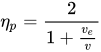
for all jet engines the propulsive efficiency is highest as the exhaust jet velocity gets closer to the vehicle speed as this gives the smallest residual kinetic energy.[a] For an airbreathing engine an exhaust velocity equal to the vehicle velocity, or a equal to one, gives zero thrust with no net momentum change.[55] The formula for air-breathing engines moving at speed with an exhaust velocity , and neglecting fuel flow, is:[56]


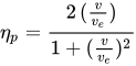
And for a rocket:[57]
In addition to propulsive efficiency, another factor is cycle efficiency; a jet engine is a form of heat engine. Heat engine efficiency is determined by the ratio of temperatures reached in the engine to that exhausted at the nozzle. This has improved constantly over time as new materials have been introduced to allow higher maximum cycle temperatures. For example, composite materials, combining metals with ceramics, have been developed for HP turbine blades, which run at the maximum cycle temperature.[58] The efficiency is also limited by the overall pressure ratio that can be achieved. Cycle efficiency is highest in rocket engines (~60+%), as they can achieve extremely high combustion temperatures. Cycle efficiency in turbojet and similar is nearer to 30%, due to much lower peak cycle temperatures.


The combustion efficiency of most aircraft gas turbine engines at sea level takeoff conditions is almost 100%. It decreases nonlinearly to 98% at altitude cruise conditions. Air-fuel ratio ranges from 50:1 to 130:1. For any type of combustion chamber there is a rich and weak limit to the air-fuel ratio, beyond which the flame is extinguished. The range of air-fuel ratio between the rich and weak limits is reduced with an increase of air velocity. If the increasing air mass flow reduces the fuel ratio below certain value, flame extinction occurs.[59]

Consumption of fuel or propellant
A closely related (but different) concept to energy efficiency is the rate of consumption of propellant mass. Propellant consumption in jet engines is measured by specific fuel consumption, specific impulse, or effective exhaust velocity. They all measure the same thing. Specific impulse and effective exhaust velocity are strictly proportional, whereas specific fuel consumption is inversely proportional to the others.[60]
For air-breathing engines such as turbojets, energy efficiency and propellant (fuel) efficiency are much the same thing, since the propellant is a fuel and the source of energy. In rocketry, the propellant is also the exhaust, and this means that a high energy propellant gives better propellant efficiency but can in some cases actually give lower energy efficiency.
It can be seen in the table (just below) that the subsonic turbofans such as General Electric's CF6 turbofan use a lot less fuel to generate thrust for a second than did the Concorde's Rolls-Royce/Snecma Olympus 593 turbojet. However, since energy is force times distance and the distance per second was greater for the Concorde, the actual power generated by the engine for the same amount of fuel was higher for the Concorde at Mach 2 than the CF6. Thus, the Concorde's engines were more efficient in terms of energy per distance traveled.
Thrust-to-weight ratio
The thrust-to-weight ratio of jet engines with similar configurations varies with scale, but is mostly a function of engine construction technology. For a given engine, the lighter the engine, the better the thrust-to-weight is, the less fuel is used to compensate for drag due to the lift needed to carry the engine weight, or to accelerate the mass of the engine.[76]
As can be seen in the following table, rocket engines generally achieve much higher thrust-to-weight ratios than duct engines such as turbojet and turbofan engines. This is primarily because rockets almost universally use dense liquid or solid reaction mass which gives a much smaller volume and hence the pressurization system that supplies the nozzle is much smaller and lighter for the same performance. Duct engines have to deal with air which is two to three orders of magnitude less dense and this gives pressures over much larger areas, which in turn results in more engineering materials being needed to hold the engine together and for the air compressor.
Comparison of types

Propeller engines handle larger air mass flows, and give them smaller acceleration, than jet engines. Since the increase in air speed is small, at high flight speeds the thrust available to propeller-driven aeroplanes is small. However, at low speeds, these engines benefit from relatively high propulsive efficiency.[89]
On the other hand, turbojets accelerate a much smaller mass flow of intake air and burned fuel, but they then reject it at very high speed. When a de Laval nozzle is used to accelerate a hot engine exhaust, the outlet velocity may be locally supersonic. Turbojets are particularly suitable for aircraft travelling at very high speeds.
Turbofans have a mixed exhaust consisting of the bypass air and the hot combustion product gas from the core engine. The amount of air that bypasses the core engine compared to the amount flowing into the engine determines what is called a turbofan's bypass ratio (BPR).
While a turbojet engine uses all of the engine's output to produce thrust in the form of a hot high-velocity exhaust gas jet, a turbofan's cool low-velocity bypass air yields between 30% and 70% of the total thrust produced by a turbofan system.[90]
The net thrust (FN) generated by a turbofan can also be expanded as:[91]

where:
Rocket engines have extremely high exhaust velocity and thus are best suited for high speeds (hypersonic) and great altitudes. At any given throttle, the thrust and efficiency of a rocket motor improves slightly with increasing altitude (because the back-pressure falls thus increasing net thrust at the nozzle exit plane), whereas with a turbojet (or turbofan) the falling density of the air entering the intake (and the hot gases leaving the nozzle) causes the net thrust to decrease with increasing altitude. Rocket engines are more efficient than even scramjets above roughly Mach 15.[92]
Altitude and speed
With the exception of scramjets, jet engines, deprived of their inlet systems can only accept air at around half the speed of sound. The inlet system's job for transonic and supersonic aircraft is to slow the air and perform some of the compression.
The limit on maximum altitude for engines is set by flammability – at very high altitudes the air becomes too thin to burn, or after compression, too hot. For turbojet engines altitudes of about 40 km appear to be possible, whereas for ramjet engines 55 km may be achievable. Scramjets may theoretically manage 75 km.[93] Rocket engines of course have no upper limit.
At more modest altitudes, flying faster compresses the air at the front of the engine, and this greatly heats the air. The upper limit is usually thought to be about Mach 5–8, as above about Mach 5.5, the atmospheric nitrogen tends to react due to the high temperatures at the inlet and this consumes significant energy. The exception to this is scramjets which may be able to achieve about Mach 15 or more, as they avoid slowing the air, and rockets again have no particular speed limit.
Noise
The noise emitted by a jet engine has many sources. These include, in the case of gas turbine engines, the fan, compressor, combustor, turbine and propelling jet/s.[94]
The propelling jet produces jet noise which is caused by the violent mixing action of the high speed jet with the surrounding air. In the subsonic case the noise is produced by eddies and in the supersonic case by Mach waves.[95] The sound power radiated from a jet varies with the jet velocity raised to the eighth power for velocities up to 600 m/s (2,000 ft/s) and varies with the velocity cubed above 600 m/s (2,000 ft/s).[96] Thus, the lower speed exhaust jets emitted from engines such as high bypass turbofans are the quietest, whereas the fastest jets, such as rockets, turbojets, and ramjets, are the loudest. For commercial jet aircraft the jet noise has reduced from the turbojet through bypass engines to turbofans as a result of a progressive reduction in propelling jet velocities. For example, the JT8D, a bypass engine, has a jet velocity of 400 m/s (1,450 ft/s) whereas the JT9D, a turbofan, has jet velocities of 300 m/s (885 ft/s) (cold) and 400 m/s (1,190 ft/s)(hot).[97]
The advent of the turbofan replaced the very distinctive jet noise with another sound known as "buzz saw" noise. The origin is the shockwaves originating at the supersonic fan blade tip at takeoff thrust.[98]
Cooling
Adequate heat transfer away from the working parts of the jet engine is critical to maintaining strength of engine materials and ensuring long life for the engine.[99]
After 2016, research is ongoing in the development of transpiration cooling techniques to jet engine components.[100]
Operation

In a jet engine, each major rotating section usually has a separate gauge devoted to monitoring its speed of rotation. Depending on the make and model, a jet engine may have an N1 gauge that monitors the low-pressure compressor section and/or fan speed in turbofan engines. The gas generator section may be monitored by an N2 gauge, while triple spool engines may have an N3 gauge as well. Each engine section rotates at many thousands RPM. Their gauges therefore are calibrated in percent of a nominal speed rather than actual RPM, for ease of display and interpretation.[101]
See also
Notes
- ↑Note: In Newtonian mechanics kinetic energy is frame dependent. The kinetic energy is easiest to calculate when the speed is measured in the center of mass frame of the vehicle and (less obviously) its reaction mass/air (i.e., the stationary frame before takeoff begins.
- ↑10% better than Trent 700
- ↑10% better than Trent 700
- ↑15 per cent fuel consumption advantage over the original Trent engine
References
- ↑"Flight Operations Briefing Notes – Supplementary Techniques : Handling Engine Malfunctions"(PDF). Airbus. Archived from the original(PDF) on 2016-10-22.
- ↑propeller efficiencyArchived May 25, 2008, at the Wayback Machine
- ↑Bakken, Lars E.; Jordal, Kristin; Syverud, Elisabet; Veer, Timot (14 June 2004). "Centenary of the First Gas Turbine to Give Net Power Output: A Tribute to Ægidius Elling". Volume 2: Turbo Expo 2004. pp. 83–88. doi:10.1115/GT2004-53211. ISBN 978-0-7918-4167-9.
- ↑"Propulseur par réaction sur l'air". Espacenet – patent search.
- ↑"Who really invented the jet engine?". BBC Science Focus Magazine. 6 July 2017. Retrieved 2019-10-18.
- ↑"Chasing the Sun – Frank Whittle". PBS. Retrieved 2010-03-26.
{{cite web}}: CS1 maint: deprecated archival service (link) - ↑"History – Frank Whittle (1907–1996)". BBC. Retrieved 2010-03-26.
- ↑"Improvements relating to the propulsion of aircraft and other vehicles". Espacenet – patent search. Archived from the original on 2022-06-21. Retrieved 2020-05-30.
- ↑Junquera, Natalia (29 May 2014). "Spain's forgotten jet-engine genius". EL PAÍS English. Retrieved 2 September 2021.
- ↑"El Museo del Aire acoge una réplica del motor a reacción que diseñó Virgilio Leret". Aerotendencias. 9 June 2014. Retrieved 2 September 2021.
- ↑The History of the Jet Engine – Sir Frank Whittle – Hans Von Ohain[link removed] Ohain said that he had not read Whittle's patent and Whittle believed him. (Frank Whittle 1907–1996).
- ↑Warsitz, Lutz: The First Jet Pilot – The Story of German Test Pilot Erich Warsitz (p. 125), Pen and Sword Books Ltd., England, 2009Archived 2013-12-02 at the Wayback Machine
- ↑Experimental & Prototype US Air Force Jet Fighters, Jenkins & Landis, 2008
- ↑Foderaro, Lisa W. (10 August 1996). "Frank Whittle, 89, Dies; His Jet Engine Propelled Progress". The New York Times.
- ↑"Anselm Franz and the Jumo 004". go.gale.com. Retrieved 2026-05-08.
- ↑"Junkers Jumo 004 Turbojet — National Museum of the United States Air Force".
- ↑"Jumo 004B Engine | National Air and Space Museum". airandspace.si.edu. Retrieved 2026-05-08.
- ↑Heaton, Colin D.; Lewis, Anne-Marien; Tillman, Barrett (15 May 2012). The Me 262 Stormbird: From the Pilots Who Flew, Fought, and Survived It. Voyageur Press. ISBN 978-1-61058434-0.
- ↑Listemann, Phil H. (6 September 2016). The Gloster Meteor F.I & F.III. Philedition. p. 5. ISBN 978-2-918590-95-8.
- ↑"The Day Germany's First Jet Fighter Soared into History".
- ↑"ch. 10-3". Hq.nasa.gov. Archived from the original on 2010-09-14. Retrieved 2010-03-26.
- ↑"The numbers behind Thrust SSC's enduring land speed record". Institution of Mechanical Engineers. Retrieved 13 July 2026.
- ↑Imani, Amin; Anjomrouz, Amin (2025). "Design and Simulation of a Control System for a Single Spool Mixed-Flow Small Turbofan Engine". Journal of Aeronautics, Astronautics and Aviation. 57 (1): 1–12. doi:10.6125/JoAAA.202501_57(1).01.
- ↑The Jet Engine (5th ed.). Rolls-Royce plc. 2015. pp. 8–15.
- ↑Mattingly, Jack D. (2006). Elements of Propulsion: Gas Turbines and Rockets. AIAA Education Series. Reston, VA: American Institute of Aeronautics and Astronautics. p. 6. ISBN 978-1-56347-779-9.
- ↑Mattingly, pp. 9–11
- ↑"Notice of Proposed Amendment 2015-22: Open rotor engine and installation". European Union Aviation Safety Agency. Retrieved 2026-05-19.
- ↑Flight International (2007-07-12). "Whatever happened to propfans?". Archived from the original on October 20, 2007. Retrieved 2024-11-28.
{{cite web}}: CS1 maint: numeric names: authors list (link) - ↑Wragg, David W. (1973). A Dictionary of Aviation (first ed.). Osprey. p. 4. ISBN 9780850451634.
- ↑Mattingly, p. 14
- ↑Flack, Ronald D. (2005). Fundamentals of Jet Propulsion with Applications. Cambridge Aerospace Series. New York: Cambridge University Press. p. 16. ISBN 978-0-521-81983-1.
- ↑Reaction engine definition, Collins online dictionary: "an engine, such as a jet or rocket engine, that ejects gas at high velocity and develops its thrust from the ensuing reaction" (UK), or "an engine, as a jet or rocket engine, that generates thrust by the reaction to an ejected stream of hot exhaust gases, ions, etc." (US) (retrieved 28 June 2018)
- ↑Jet propulsion, Collins online dictionary definition. (retrieved 1 July 2018)
- ↑AC Kermode; Mechanics of Flight, 8th Edition, Pitman 1972, pp. 128–31.
- ↑"Rocket Thrust Equation". Grc.nasa.gov. 2008-07-11. Retrieved 2010-03-26.
- ↑"Overview of the Turbine Based Combined Cycle Discipline". NASA Technical Reports Server. Retrieved 19 April 2026.
- ↑Jet Propulsion for Aerospace Applications Second Edition 1964, Hesse and Mumford, Pitman Publishing Corporation, LCCN 64-18757, p. 48
- ↑"Jet Propulsion" Nicholas Cumpsty 1997, Cambridge University Press, ISBN 0-521-59674-2, p. 197
- ↑"AEHS Conventions 1". www.enginehistory.org.
- ↑Gamble, Eric; Terrell, Dwain; DeFrancesco, Richard (2004). "Nozzle Selection and Design Criteria". 40th AIAA/ASME/SAE/ASEE Joint Propulsion Conference and Exhibit. American Institute of Aeronautics and Astronautics. doi:10.2514/6.2004-3923. ISBN 978-1-62410-037-6.
- ↑Design For Air Combat" Ray Whitford Jane's Publishing Company Ltd. 1987, ISBN 0-7106-0426-2, p. 203
- ↑"Jet Propulsion" Nicholas Cumpsty 1997, Cambridge University Press, ISBN 0-521-59674-2, p. 141
- ↑Gas Turbine Performance Deterioration, Meher-Homji, Chaker and Motiwala, Proceedings Of The 30th Turbomachinery Symposium, ASME, pp. 139–175
- ↑"Jet Propulsion' Nicholas Cumpsty, Cambridge University Press 2001, ISBN 0-521-59674-2, Figure 9.1 shows losses with incidence
- ↑"Jet Propulsion' Nicholas Cumpsty, Cambridge University Press 2001, ISBN 0-521-59674-2, p. 35
- ↑Gas Turbine Performance' Second Edition, Walsh and Fletcher, Blackwell Science Ltd., ISBN 0-632-06434-X, p. 64
- ↑"Jet Propulsion' Nicholas Cumpsty, Cambridge University Press 2001, ISBN 0-521-59674-2, p. 26
- ↑"Archived copy"(PDF). Archived from the original(PDF) on 2016-05-09. Retrieved 2016-05-16.
{{cite web}}: CS1 maint: archived copy as title (link) Figure 22 Inlet Pressure Recovery - ↑B-70 Aircraft Study Final Report Volume IV, SD 72-SH-0003 April 1972, L.J.Taube, Space Division North American Rockwell, pp. iv–11
- ↑"Design For Air Combat" Ray Whitford, Jane's Publishing Company Limited 1987, ISBN 0-7106-0426-2, p. 203 'Area ratio for optimum expansion'
- ↑Gas Turbine Performance' Second Edition, Walsh and Fletcher, Blackwell Science Ltd., ISBN 0-632-06535-4, p. 305
- ↑Aero engine development for the future, Bennett, Proc Instn Mech Engrs Vol 197A, IMechE July 1983, Fig.5 Overall spectrum of engine losses
- ↑Gas Turbine Theory Second Edition, Cohen, Rogers and Saravanamuttoo, Longman Group Limited 1972, ISBN 0-582-44927-8, p.
- ↑Aero engine development for the future, Bennett, Proc Instn Mech Engrs Vol 197A, IMechE July 1983, p. 150
- ↑"Jet Propulsion for Aerospace Applications' Second Edition, Hesse and Mumford, Piman Publishing Corporation 1964, LCCN 64-18757, p. 39
- ↑"Jet Propulsion" Nicholas Cumpsty ISBN 0-521-59674-2 p. 24
- ↑George P. Sutton and Oscar Biblarz (2001). Rocket Propulsion Elements (7th ed.). John Wiley & Sons. pp. 37–38. ISBN 978-0-471-32642-7.
- ↑S. Walston, A. Cetel, R. MacKay, K. O’Hara, D. Duhl, and R. Dreshfield (2004). Joint Development of a Fourth Generation Single Crystal SuperalloyArchived 2006-10-15 at the Wayback Machine. NASA TM – 2004-213062. December 2004. Retrieved: 16 June 2010.
- ↑Claire Soares, "Gas Turbines: A Handbook of Air, Land and Sea Applications", p. 140.
- ↑"Rocket Engines – Introduction to Aerospace Flight Vehicles". Embry-Riddle Aeronautical University. Retrieved 2026-06-15.
- ↑"NK33". Encyclopedia Astronautica.
- ↑"SSME". Encyclopedia Astronautica.
- 123456789101112131415161718192021222324252627282930313233Nathan Meier (21 Mar 2005). "Military Turbojet/Turbofan Specifications". Archived from the original on 11 February 2021.
- 12"Flanker". AIR International Magazine. 23 March 2017.
- 12"EJ200 turbofan engine"(PDF). MTU Aero Engines. April 2016.
- 1234567891011Kottas, Angelos T.; Bozoudis, Michail N.; Madas, Michael A. "Turbofan Aero-Engine Efficiency Evaluation: An Integrated Approach Using VSBM Two-Stage Network DEA"(PDF). doi:10.1016/j.omega.2019.102167.
- 123Élodie Roux (2007). "Turbofan and Turbojet Engines: Database Handbook"(PDF). p. 126. ISBN 9782952938013.
- 1234567891011Nathan Meier (3 Apr 2005). "Civil Turbojet/Turbofan Specifications". Archived from the original on 17 August 2021.
- 12Ilan Kroo. "Data on Large Turbofan Engines". Aircraft Design: Synthesis and Analysis. Stanford University. Archived from the original on 11 January 2017.
- 123David Kalwar (2015). "Integration of turbofan engines into the preliminary design of a high-capacity short-and medium-haul passenger aircraft and fuel efficiency analysis with a further developed parametric aircraft design software"(PDF).
- ↑"Purdue School of Aeronautics and Astronautics Propulsion Web Page - TFE731".
- 12Lloyd R. Jenkinson & al. (30 Jul 1999). "Civil Jet Aircraft Design: Engine Data File". Elsevier/Butterworth-Heinemann.
- 1234"Gas Turbine Engines"(PDF). Aviation Week. 28 January 2008. pp. 137–138.
- ↑Élodie Roux (2007). "Turbofan and Turbojet Engines: Database Handbook". ISBN 9782952938013.
- 12Vladimir Karnozov (August 19, 2019). "Aviadvigatel Mulls Higher-thrust PD-14s To Replace PS-90A". AIN Online.
- ↑"Jet engine". www.airports-worldwide.com. Retrieved 2026-06-15.
- ↑Wade, Mark. "RD-0410". Encyclopedia Astronautica. Retrieved 2009-09-25.
- ↑РД0410. Ядерный ракетный двигатель. Перспективные космические аппараты[RD0410. Nuclear Rocket Engine. Advanced launch vehicles]. KBKhA - Chemical Automatics Design Bureau. Archived from the original on 30 November 2010.
- ↑"Aircraft: Lockheed SR-71A Blackbird". Archived from the original on 2012-07-29. Retrieved 2010-04-16.
- ↑"Factsheets : Pratt & Whitney J58 Turbojet". National Museum of the United States Air Force. Archived from the original on 2015-04-04. Retrieved 2010-04-15.
- ↑"Rolls-Royce SNECMA Olympus - Jane's Transport News". Archived from the original on 2010-08-06. Retrieved 2009-09-25.
With afterburner, reverser and nozzle ... 3,175 kg ... Afterburner ... 169.2 kN
- ↑Military Jet Engine Acquisition, RAND, 2002.
- ↑"Конструкторское бюро химавтоматики" - Научно-исследовательский комплекс / РД0750.[«Konstruktorskoe Buro Khimavtomatiky» - Scientific-Research Complex / RD0750.]. KBKhA - Chemical Automatics Design Bureau. Archived from the original on 26 July 2011.
- ↑Wade, Mark. "RD-0146". Encyclopedia Astronautica. Retrieved 2009-09-25.
- ↑SSME
- ↑"RD-180". Retrieved 2009-09-25.
- ↑Encyclopedia Astronautica: F-1
- ↑Astronautix NK-33 entry
- ↑"Turboprop Thrust". www.grc.nasa.gov. Archived from the original on 2026-04-30. Retrieved 2026-06-15.
- ↑Federal Aviation Administration (FAA) (2004). FAA-H-8083-3B Airplane Flying Handbook Handbook(PDF). Federal Aviation Administration. Archived from the original(PDF) on 2012-09-21.
- ↑"Turbofan Thrust". Archived from the original on 2010-12-04. Retrieved 2012-07-24.
- ↑"Microsoft PowerPoint – KTHhigspeed08.ppt"(PDF). Archived from the original(PDF) on 2009-09-29. Retrieved 2010-03-26.
- ↑"Scramjet". Orbitalvector.com. 2002-07-30. Archived from the original on 2016-02-12. Retrieved 2010-03-26.
- ↑"Softly, softly towards the quiet jet" Michael J. T. Smith New Scientist 19 February 1970 p. 350
- ↑"Silencing the sources of jet noise" Dr David Crighton New Scientist 27 July 1972 p. 185
- ↑"Noise" I.C. Cheeseman Flight International 16 April 1970 p. 639
- ↑"The Aircraft Gas Turbine Engine and its operation" United Technologies Pratt & Whitney Part No. P&W 182408 December 1982 Sea level static internal pressures and temperatures pp. 219–220
- ↑'Quietening a Quiet Engine – The RB211 Demonstrator Programme" M.J.T. Smith SAE paper 760897 "Intake Noise Suppression" p. 5
- ↑Jackowski, Thomas (2026-04-16). "Karlsruhe Institute of Technology (KIT) - Institute of Thermal Turbomachinery (ITS) Research - Research focus - Low-cycle fatigue phenomena on engine components". www.its.kit.edu. Retrieved 2026-06-15.
- ↑Transpiration Cooling Systems for Jet Engine Turbines and Hypersonic Flight, accessed 30 January 2019.
- ↑"15 - Operating the Jet Engine". Airplane flying handbook(PDF). FAA. 25 July 2017. p. 3. ISBN 9781510712843. OCLC 992171581.
 This article incorporates public domain material from websites or documents of the Federal Aviation Administration.
Bibliography
- Brooks, David S. (1997). Vikings at Waterloo: Wartime Work on the Whittle Jet Engine by the Rover Company. Rolls-Royce Heritage Trust. ISBN 978-1-872922-08-9.
- Golley, John (1997). Genesis of the Jet: Frank Whittle and the Invention of the Jet Engine. Crowood Press. ISBN 978-1-85310-860-0.
- Hill, Philip; Peterson, Carl (1992), Mechanics and Thermodynamics of Propulsion (2nd ed.), New York: Addison-Wesley, ISBN 978-0-201-14659-2
- Kerrebrock, Jack L. (1992). Aircraft Engines and Gas Turbines (2nd ed.). Cambridge, MA: The MIT Press. ISBN 978-0-262-11162-1.
External links
 Media related to Jet engines at Wikimedia Commons
 The dictionary definition of jet engine at Wiktionary
- Media about jet engines from Rolls-Royce
- How Stuff Works article on how a Gas Turbine Engine works
- Influence of the Jet Engine on the Aerospace Industry
- An Overview of Military Jet Engine History, Appendix B, pp. 97–120, in Military Jet Engine Acquisition (Rand Corp., 24 pp, PDF)
- Basic jet engine tutorial (QuickTime Video)
- An article on how reaction engine works
- The Aircraft Gas Turbine Engine and Its Operation: Installation Engineering. East Hartford, Connecticut: United Aircraft Corporation. February 1958. Retrieved 29 September 2021.
- Fusion Powered Jet Engine and Airplane
- Energy conversion
- Gas turbines
- Jet engines
- Compressors
- Turbomachinery
- Engineering thermodynamics
- Fluid dynamics
- Aerodynamics
- Discovery and invention controversies
- 20th-century inventions