 Hispanopedia Wiki
Una antena de bucle es una antena de radio que consiste en un bucle o bobina de alambre, tubo u otro conductor eléctrico , que para transmitir se alimenta generalmente con una fuente de alimentación balanceada o para recibir alimenta una carga balanceada. Las antenas de bucle se pueden dividir en tres categorías:
Antenas de bucle grandes : También llamadas antenas de bucle autorresonantes o bucles de onda completa ; tienen un perímetro cercano a una o más longitudes de onda completas a la frecuencia de operación , lo que las hace autorresonantes [ a ] a esa frecuencia. Las antenas de bucle grandes tienen un patrón de radiación dipolar de dos lóbulos en su primera resonancia de onda completa, con picos en ambas direcciones perpendiculares al plano del bucle. [ b ]
Antenas de halo : Las antenas de halo suelen describirse como dipolos acortados que se han doblado formando un bucle circular, con los extremos sin llegar a tocarse. Algunos autores prefieren excluirlas de las antenas de bucle, ya que pueden entenderse perfectamente como dipolos doblados ; otros las consideran una categoría intermedia entre los bucles grandes y pequeños, o el límite superior de tamaño para los bucles transmisores pequeños . En forma y rendimiento, las antenas de halo son muy similares a los bucles pequeños, diferenciándose únicamente por ser autorresonantes y tener una resistencia a la radiación mucho mayor . (Véase la explicación a continuación ).
Antenas de bucle pequeño : También llamadas bucles magnéticos o bucles sintonizados ; tienen un perímetro menor que la mitad de la longitud de onda de operación (típicamente no más de 1/3 a 1/4 de onda ) . Se utilizan principalmente como antenas receptoras debido a su baja eficiencia, pero a veces se utilizan para transmisión; los bucles con una circunferencia menor que aproximadamente 1/10 de la longitud de onda se vuelven tan ineficientes que rara vez se utilizan para transmisión. [ c ] Un ejemplo común de bucle pequeño es la antena de ferrita (loopstick) utilizada en la mayoría de las radios de difusión AM. [ d ] El patrón de radiación de las antenas de bucle pequeño es máximo en las direcciones dentro del plano del bucle, por lo que es perpendicular a los máximos de los bucles grandes.
Antenas de bucle grandes y autorresonantes
Para la descripción de bucles grandes en esta sección, se supone que la frecuencia de operación de la radio está sintonizada a la primera resonancia de la antena de bucle. A esa frecuencia, una longitud de onda completa en el espacio libre es ligeramente menor que el perímetro del bucle, que es el tamaño mínimo que puede tener un bucle "grande". [ 2 ]
Las antenas de bucle autorresonantes para las llamadas frecuencias de onda "corta" son relativamente grandes, con un perímetro ligeramente mayor que la longitud de onda de operación prevista; por lo tanto, para bucles circulares, los diámetros oscilan entre aproximadamente 53 metros (175 pies ) en el caso de las más grandes, alrededor de 1,8 MHz . A frecuencias más altas, su tamaño se reduce, llegando a un diámetro de unos 3,4 metros (11 pies ) a 30 MHz.
Las grandes antenas de bucle pueden considerarse como dipolos plegados cuyos cables paralelos se han separado y abierto formando una figura ovalada o poligonal . La forma del bucle puede ser un círculo, un triángulo, un cuadrado, un rectángulo o, de hecho, cualquier polígono cerrado, pero para que se produzca la resonancia, el perímetro del bucle debe ser ligeramente mayor que una longitud de onda. [ 2 ]
Forma

Las antenas de bucle pueden tener forma circular, cuadrada o cualquier otra forma geométrica cerrada que permita que el perímetro total sea ligeramente superior a una longitud de onda. La forma más popular en la radioafición es la antena quad o "quad", un bucle autorresonante de forma cuadrada que se puede construir con alambre tendido a través de un marco de soporte en forma de × . Puede haber uno o más bucles adicionales apilados en paralelo al primero como elementos directores o reflectores "parásitos" , creando una matriz de antenas unidireccional con una ganancia que aumenta con cada elemento parásito adicional. Este diseño también se puede girar 45 grados para formar un diamante soportado por un marco en forma de + . También se han utilizado bucles triangulares ( en forma de △ ) para bucles verticales, ya que se pueden soportar desde un solo mástil. [ 2 ] Un rectángulo con el doble de altura que de ancho obtiene una ganancia ligeramente mayor y también se adapta directamente a 50 Ω si se utiliza como un solo elemento. [ 2 ] : § 9.6.2
A diferencia de una antena dipolo , la polarización de una antena de bucle resonante no es evidente a partir de la orientación del bucle en sí, sino que depende de la ubicación de su punto de alimentación. [ e ] Si un bucle orientado verticalmente se alimenta en la parte inferior, su radiación estará polarizada horizontalmente; si se alimenta desde un lado, estará polarizada verticalmente.
Patrón de radiación
El patrón de radiación de una antena de bucle de primera resonancia presenta un pico perpendicular al plano del bucle. A medida que la frecuencia aumenta hacia la segunda y tercera resonancia, la radiación perpendicular disminuye y aparecen lóbulos intensos cerca del plano del bucle. [ 3 ] (p235)
En las frecuencias de onda corta más bajas, una antena de bucle completo es físicamente bastante grande, y su única instalación práctica es "en posición horizontal", con el plano del bucle paralelo al suelo y el cable de la antena sostenido a la misma altura relativamente baja por mástiles a lo largo de su perímetro. [ 2 ] Esto da como resultado una radiación polarizada horizontalmente, que alcanza su máximo hacia la vertical cerca del armónico más bajo; este patrón es bueno para la comunicación regional NVIS , pero desafortunadamente no suele ser útil para establecer contactos a escala continental.
Por encima de los 10 MHz, la antena de bucle tiene un diámetro aproximado de 10 metros, por lo que resulta más práctico montarla en posición vertical (con el plano del bucle en vertical) para dirigir su haz principal hacia el horizonte. Si la frecuencia es suficientemente alta, el bucle puede ser lo suficientemente pequeño como para acoplarse a un rotor de antena y así orientarlo según se desee. En comparación con un dipolo o un dipolo plegado, un bucle vertical de gran tamaño desperdicia menos potencia irradiando hacia el cielo o el suelo, lo que se traduce en una ganancia aproximadamente 1,5 dB mayor en las dos direcciones horizontales preferidas.
Generalmente se obtiene una ganancia adicional (y un patrón de radiación unidireccional ) con una matriz de estos elementos, ya sea como una matriz de radiación frontal activada o en una configuración Yagi , donde solo uno de los bucles es alimentado por la línea de transmisión y todos los demás actúan como reflectores y directores "parásitos" . Esta última configuración es muy utilizada en la radioafición en la configuración "quad" (ver foto).
En ocasiones, se utilizan antenas de bucle de baja frecuencia y una longitud de onda, dispuestas horizontalmente, para comunicaciones NVIS locales. A esto se le denomina a veces antena cuadrilátera perezosa . Su patrón de radiación consiste en un único lóbulo que apunta directamente hacia arriba (la radiación que se dirige al suelo y no se absorbe se refleja hacia arriba). El patrón de radiación, y especialmente la impedancia de entrada, se ve afectado por su proximidad al suelo.
Si se alimenta con frecuencias más altas, la impedancia de entrada de la antena generalmente incluirá una parte reactiva y un componente resistivo diferente, lo que requiere el uso de un sintonizador de antena . A medida que la frecuencia aumenta por encima del primer armónico, el patrón de radiación se divide en múltiples lóbulos que alcanzan su máximo en ángulos menores con respecto al horizonte, lo que supone una mejora para la comunicación a larga distancia en frecuencias muy superiores al segundo armónico del bucle.
Antenas Halo
A halo antenna is often described as a half-wave dipole antenna that has been bent into a circle. Although it could be categorized as a bent dipole, it has the omnidirectional radiation pattern very nearly the same as a small loop. The halo is more efficient than a small loop, since it is a larger antenna at 1/ 2 wave in circumference with its disproportionately larger radiation resistance.[f] Because of its much greater radiation resistance, a halo presents a good impedance match to 50-Ohm coaxial cable, and its construction is less demanding than a small loop, since the maker is not compelled to take such extreme care to avoid losses from mediocre conductors and contact resistance.[4]
At 1/ 2 wave, the halo antenna is near or on the extreme high limit of the size range for "small" loops, but unlike most oversized small loops, it can be analyzed with simple techniques by treating it as a bent dipole.
Practical use

On the VHF bands and above, the physical diameter of a halo is small enough to be effectively used as a mobile antenna.
The horizontal radiation pattern of a horizontal halo is nearly omnidirectional – to within 3 dB or less – and that can be evened out by making the loop slightly smaller and adding more capacitance between the element tips. Not only will that even out the gain, it will reduce upward radiation, which for VHF is typically wasted by radiating into space.
Halos pick up less nearby electrical spark interference than monopoles and dipoles, such as ignition noise from vehicles.[5]
Electrical analysis
Although it has a superficially different appearance, the halo antenna can conveniently be analyzed as a dipole (which also has a half-wave radiating part with a high voltage and zero current at its ends) that has been bent into a circle. Simply using dipole results greatly simplifies the calculations and for most properties are the same as a halo. Halo performance can also be modeled with techniques used for similar, moderate-sized "small" transmitting loops, but for brevity, that complicated analysis is often skipped in introductory articles on loop antennas (unfortunately, this typical omission leaves otherwise well-read persons unaware of the properties of "large" small loops).
The halo's gap
Some writers mistakenly consider the gap in the halo antenna's loop to distinguish it from a small loop antenna, since there is no DC connection between the two ends. But that distinction is lost at RF; the close-bent high-voltage ends are capacitively coupled, and the RF current crosses the gap as displacement current. The gap in the halo is electrically equivalent to the tuning capacitor on a small loop, although the incidental capacitance involved is not nearly as large.[g]
Small loops

Small loops are "small" in comparison to their operating wavelength. Contrary to the pattern of large loop antennas, the reception and radiation strength of small loops peaks inside the plane of the loop, rather than broadside (perpendicular) to it.[3]:235
As with all antennas that are physically much smaller than the operating wavelength, small loop antennas have small radiation resistance which is dwarfed by ohmic losses, resulting in a poor antenna efficiency. They are thus mainly used as receiving antennas at lower frequencies (wavelengths of tens to hundreds of meters). Like a short dipole antenna, the radiation resistance is small. The radiation resistance is proportional to the square of the area:

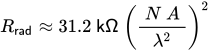
where A is the area enclosed by the loop, λ is the wavelength, and N is the number of turns of the conductor around the loop.
Because of the higher exponent than linear antennas (loop area squared ≈ perimeter to the 4th power, vs. dipole & monopole length squared = 2nd power), the fall in Rrad with reduced size is more extreme.[6]:5‑11 The ability to increase the radiation resistance Rrad by using multiple turns is analogous to making a dipole out of two or more parallel lines for each dipole arm ("folded dipole").
Small loops have advantages as receiving antennas at frequencies below 10 MHz.[7] Although a small loop's losses can be high, the same loss applies to both the signal and the noise, so the receiving signal-to-noise ratio of a small loop may not suffer at these lower frequencies, where received noise is dominated by atmospheric noise and static rather than receiver-internal noise. The ability to more manageably rotate a smaller antenna may help to maximize the signal and reject interference. Several construction techniques are used to ensure that small receiving loops' null directions are "sharp", including adding broken shielding of the loop arms and keeping the perimeter around 1/ 10 wavelength (or 1/4 wave at most). Small transmitting loops' perimeters are instead made as large as feasibly possible, up to 1/3 wave (or even 1/2 if possible), in order to make the best of their generally poor efficiency, although doing so sacrifices sharp nulls.
The small loop antenna is also known as a magnetic loop since the response of an electrically small receiving loop is proportional to the rate of change of magnetic flux through the loop.[8] At higher frequencies (or shorter wavelengths), when the antenna is no longer electrically small, the current distribution through the loop may no longer be uniform and the relationship between its response and the incident fields becomes more complicated.[8] In the case of transmission, the fields produced by an electrically small loop are the same as an "infinitesimal magnetic dipole" whose axis is perpendicular to the plane of the loop.[3]:235
Because of their meager radiation resistance, the properties of small loops tend to more often be intensively optimized than are full-size antennas, and the properties optimized for transmitting are not quite the same as for receiving. With full-size antennas, the reciprocity between transmitting and receiving usually makes the distinctions unimportant, but since a few RF properties important for receiving differ from those for transmitting – particularly below about 10~20 MHz – small loops intended for receiving have slight differences from small transmitting loops. They are discussed separately in following two subsections, although many of the comments apply to both.
Small receiving loops

If the perimeter of a loop antenna is much smaller than the intended operating wavelengths – say 1/ 8 to 1/ 100 of a wavelength – then the antenna is called a small receiving loop, since loop antennas that small are only practical for receiving. Several performance factors, including received power, scale in proportion to the loop's area. For a given loop area, the length of the conductor (and thus its net loss resistance) is minimized if the perimeter is circular, making a circle the optimal shape for small loops. Small receiving loops are typically used below 14 MHz, where human-made and natural atmospheric noise dominate. Thus the signal-to-noise ratio of the received signal will not be adversely affected by low efficiency as long as the loop is not excessively small.
A typical diameter of receiving loops with "air centers" is between 30 and 100 cm (1 and 3.5 feet). To increase the magnetic field in the loop and thus its efficiency, while greatly reducing size, the coil of wire is often wound around a ferrite rod magnetic core; this is called a ferrite loop antenna. Such ferrite loop antennas are used in almost all AM broadcast receivers with the notable exception of car radios, since the antenna for the AM band needs to be outside the obstructing metal car chassis.
Small loop antennas are also popular for radio direction finding, in part due to their exceedingly sharp, clear "null" along the loop axis: When the loop axis is aimed directly at the transmitter, the target signal abruptly vanishes.[9]

The radiation resistanceRrad of a small loop is generally much smaller than the loss resistance Rℓoss due to the conductors composing the loop, leading to a poor antenna efficiency.[h] Consequently, most of the power delivered to a small loop antenna will be converted to heat by the loss resistance, rather than doing useful work pushing out radio waves or gathering them in.
Wasted power is undesirable for a transmitting antenna, however for a receiving antenna, the inefficiency is not important at frequencies below about 15 MHz. At these lower frequencies, due to atmospheric noise (static) and man-made noise (interference), even a weak signal from an inefficient antenna is far stronger than the internal thermal or Johnson noise generated in the radio receiver's own circuitry, so the weak signal from a loop antenna can be amplified without degrading the signal-to-noise ratio, since both are magnified by the same amplification factor.[10]
For example, at 1 MHz, the man-made noise might be 55 dB above the thermal noise floor. If a small loop antenna's loss is 50 dB (as if the antenna included a 50 dB attenuator), then the electrical inefficiency of that antenna will have little influence on the receiving system's signal-to-noise ratio. In contrast, at quieter frequencies at about 20 MHz and above, an antenna with a 50 dB loss could degrade the received signal-to-noise ratio by up to 50 dB, resulting in terrible performance.
However, as frequency rises, there is no need to suffer bad performance: At the higher, quieter frequencies, the wavelengths become short enough that a halo antenna is small enough to be feasible – at 20 MHz it is a little less than 8 feet (2.4 m) in diameter, and proportionally shrinks as the frequency increases. So the quieter the rising frequency gets, the more convenient it is to replace a small receiving loop with a larger, but still relatively compact, halos. It is mostly a direct substitute for a small receiving loop, but with superior signal reception.[i]
Radiation pattern and polarization

Surprisingly, the radiation and receiving pattern of a small loop is perpendicular to that of a large self resonant loop (whose perimeter is close to one wavelength). Since the loop is much smaller than a wavelength, the current at any one moment is nearly constant round the circumference. By symmetry it can be seen that the voltages induced in the loop windings on opposite sides of the loop will cancel each other when a perpendicular signal arrives on the loop axis. Therefore, there is a null in that direction.[11] Instead, the radiation pattern peaks in directions lying in the plane of the loop, because signals received from sources in that plane do not quite cancel owing to the phase difference between the arrival of the wave at the near and far sides of the loop. Increasing that phase difference by increasing the size of the loop causes a disproportionately large increase in the radiation resistance and the resulting antenna efficiency.
Another way of looking at a small loop as an antenna is to consider it simply as an inductive coil coupling to the magnetic field in the direction perpendicular to plane of the coil, according to Ampère's law. Then consider a propagating radio wave also perpendicular to that plane. Since the magnetic (and electric) fields of an electromagnetic wave in free space are transverse (no component in the direction of propagation), it can be seen that this magnetic field and that of a small loop antenna will be at right angles, and thus not coupled. For the same reason, an electromagnetic wave propagating within the plane of the loop, with its magnetic field perpendicular to that plane, is coupled to the magnetic field of the coil. Since the transverse magnetic and electric fields of a propagating electromagnetic wave are at right angles, the electric field of such a wave is also in the plane of the loop, and thus the antenna's polarization (which is always specified as being the orientation of the electric, not the magnetic field) is said to be in that plane.
Thus, mounting the loop in a horizontal plane will produce an omnidirectional antenna which is horizontally polarized; mounting the loop vertically yields a vertically polarized, weakly directional antenna, but with exceptionally sharp nulls along the axis of the loop.[j] Size criteria that favor loops with a perimeter of 1/ 4 wave or smaller ensure the sharpness of the loop's receiving null. Small loops intended for transmitting (see below) are designed as large as feasible to improve the marginal radiation resistance, sacrificing the sharp null by using perimeters as large as 1/ 3 to 1/ 2 wave.
Receiver input tuning
Since a small-loop antenna is essentially a coil, its electrical impedance is inductive, with an inductive reactance much greater than its radiation resistance. In order to couple to a transmitter or receiver, the inductive reactance is normally canceled with a parallel capacitance.[k] Since a good loop antenna will have a high Q factor (narrow bandwidth), the capacitor must be variable and is adjusted to match the receiver's tuning.
Small-loop receiving antennas are also almost always resonated using a parallel-plate capacitor, which makes their reception narrow-band, sensitive only to a very specific frequency. This allows the antenna, in conjunction with a (variable) tuning capacitor, to act as a tuned input stage to the receiver's front-end, in lieu of a preselector.
Direction finding with small loops

As long as the loop perimeter is kept below about 1/4 wave, the directional response of small loop antennas includes a sharp null in the direction normal to the plane of the loop, so small loops are favored as compact radio direction finding antennas for long wavelengths.
The procedure is to rotate the loop antenna to find the direction where the signal vanishes – the "null" direction. Since the null occurs at two opposite directions along the axis of the loop, other means must be employed to determine which side of the antenna the nulled signal is on. One method is to rely on a second loop antenna located at a second location, or to move the receiver to that other location, thus relying on triangulation.
Instead of triangulation, a second dipole or vertical antenna can be electrically combined with a loop or a loopstick antenna. Called a sense antenna, connecting and matching the second antenna changes the combined radiation pattern to a cardioid, with a null in only one (less precise) direction. The general direction of the transmitter can be determined using the sense antenna, and then disconnecting the sense antenna returns the sharp nulls in the loop antenna pattern, allowing a precise bearing to be determined.
AM broadcast receiving antennas
Small-loop antennas are lossy and inefficient for transmitting, but they can be practical receiving antennas in the mediumwave (520–1710 kHz) broadcast band and below, where wavelength-sized antennas are infeasibly large, and the antenna inefficiency is irrelevant, due to large amounts of atmospheric noise.
AM broadcast receivers (and other low frequency radios for the consumer market) typically use small-loop antennas, even when a telescoping antenna may be attached for FM reception.[12] A variable capacitor connected across the loop forms a resonant circuit that also tunes the receiver's input stage as that capacitor tracks the main tuning. A multiband receiver may contain tap points along the loop winding in order to tune the loop antenna at widely different frequencies.
In AM radios built prior to the invention of ferrite in the mid-20th century, the antenna might consist of dozens of turns of wire mounted on the back wall of the radio – a planar helical antenna – or a separate, rotatable, furniture-sized rack looped with wire – a frame antenna.
Ferrite loop antenna

Ferrite loop antennas are made by winding fine wire around a ferrite rod. They are almost universally used in AM broadcast receivers.[12](p23)[d] Other names for this type of antenna are loopstick, ferrite rod antenna or aerial, ferroceptor, or ferrod antenna. Often, at mediumwave and lower shortwave frequencies, Litz wire is used for the winding to reduce skin effect losses. Elaborate "basket weave" patterns are used at all frequencies to reduce inter-winding capacitance in the coil insuring that the loop self-resonance is well above the operating frequency, so that it acts as an electrical inductor that can be resonated with a tuning capacitor, and with a consequent improvement of the loop Q factor.
Inclusion of a magnetically permeable core increases the radiation resistance of a small loop,[1] mitigating the inefficiency due to ohmic losses. Like all small antennas, such antennas are tiny compared to their effective area. A typical AM broadcast radio loop antenna wound on ferrite may have a cross sectional area of only 1 cm2 (0.16 sq in) at a frequency at which an ideal (lossless) antenna would have an effective area some hundred million times larger. Even accounting for the resistive losses in a ferrite rod antenna, its effective receiving area may exceed the loop's physical area by a factor of 100.[13]
Small transmitting loops
Small transmitting loops are "small" in comparison to a full wavelength, but considerably larger than a "small" receive-only loop. They are typically used on frequencies between 14 and 30 MHz. Unlike receiving loops, small transmitting loops' sizes must be scaled-up for longer wavelengths, in order to keep radiation resistance from falling to unusably low levels; their larger sizes blur or erase the otherwise especially sharp nulls that small receiving loops provide.
Size, shape, efficiency, and pattern

Transmitting loops usually consist of a single turn of large-diameter conductor; they are typically round or octagonal to maximize the enclosed area for a given perimeter, hence maximizing radiation resistance. The smaller of these loops are much less efficient than the extraordinary performance of full-sized, self-resonant loops,[14] or the moderate efficiency of monopoles, dipoles, and halos, but where space for a full wave loop or a half-wave dipole is not available, small loops can provide adequate communications with low-but-tolerable efficiency.[15][16]
A small transmitting loop antenna with a perimeter of 10% or less of the wavelength will have a relatively constant current distribution along the conductor,[1] and the main lobe will be in the plane of the loop, so it will show the null familiar in the radiation pattern of small receiving loops, but more like signal dimming, instead of complete signal loss shown by sub-1/ 10 wave direction-finding loops. Loops of any size between 10% and 30% of a wavelength in perimeter, up to almost exactly 50% in circumference, can be built and tuned with series capacitors to resonance, but their non-uniform current will reduce or eliminate the small loops' pattern null. A capacitor is required for a circumference less than a half wave, and an inductor is required for loops more than a half wave and less than a full wave.
Loops in the small transmitting loops' size range may have neither the uniform current of very small loops, nor the sinusoidal current of large loops, and thus cannot be analyzed using the assumptions useful for the small receiving loops nor full-wave loop antennas. Performance is most conveniently determined using NEC analysis. Antennas within this size range include the halo (see above) and the G0CWT (Edginton) loop. For brevity, introductory articles on small loop antennas sometimes confine discussion to loops smaller in circumference than 1/ 10 wavelength, since for loops with circumferences larger than 1/ 10 wave, the simplifying assumption of uniform current around the entire loop becomes untenably inaccurate. Since the larger halo also has a simple analysis, moderate-sized small-loop antennas and their complicated analysis are often omitted, leaving many otherwise-well-informed antenna builders in the dark regarding the performance obtainable with moderately small loops.
Use for land-mobile radio
Vertically aligned small loops are used in military land-mobile radio, at frequencies of 3–7 MHz, because of their ability to direct energy upwards, unlike a conventional whip antenna. This enables near vertical incidence skywave (NVIS) communication up to 300 km (190 miles) in mountainous regions. For NVIS, a typical radiation efficiency of around 1% is acceptable, because signal paths can be established with 1 W of radiated power or less – feasible when a 100 W transmitter is used.
In military use, the antenna may be built using a one- or two-conductor 2.5–5 cm (1–2 inches) in diameter. The loop itself is typically 1.8 m (6 feet) in diameter.
Power limits and RF safety
One practical issue with small loops as transmitting antennas is that a small transmitting loop has not only a very large current going through it, but also a very high voltage across the capacitor – typically thousands of volts – even when fed with only a few watts of transmitter power. The smaller the loop (in wavelengths), the higher the voltage. This requires a rather expensive and physically large resonating capacitor with a large breakdown voltage, in addition to having minimal dielectric loss (normally requiring an air-gap capacitor or even a vacuum variable capacitor).

Making the loop larger in diameter will lower the gap voltage, as well as improving efficiency; however, all other efficiency improvements will tend to increase the gap voltage: efficiency may be increased by making the loop from a thicker conductor; other measures to lower the conductor's loss resistance include welding or brazing the connections, rather than soldering. But because reducing loss resistance increases the antenna's Q, the consequence of better efficiency is even greater voltage across the capacitor at the loop's gap. For a given frequency, a smaller small loop is more dangerous than a larger small loop, and perversely, a comparatively efficient small transmitting loop is more dangerous than an inefficient one.
The RF burn and shock problems raised by capacitive loading of small loops is more serious than for inductive loading of short whips or dipole antennas.[l] The high antenna voltage is generally troublesome only on the upper end of a whip's loading coil, since it is spread across the extended coil length, whereas high voltages on a loop's capacitor plates are (ideally) at maximum over all of the plate surfaces. Further, the high-voltage tips of monopoles and dipoles typically are mounted high up and far out of reach, which limits opportunities for radio-frequency burns. In contrast, small-loop / "magnetic" antennas better tolerate being mounted close to the ground,[m] so all parts of loop antennas, including the high-voltage parts, are more often within easy reach.
In summary: the high voltages from high Q pose a greater threat in small loops than most other small antennas, and demand greater caution, even for very low transmit power.
Feeder loops
In addition to other common impedance matching techniques such as a gamma match, small receiving and transmitting loops are sometimes impedance-matched by connecting the feedline to an even smaller feeder loop inside the area surrounded by the main loop. Although it may still be connected through the ground system, this leaves the main loop with no other DC connection to the transmitter.[16] The feeder loop and the main loop are effectively the primary and secondary coils of a transformer, with power in the near-field inductively coupled from the feed loop into the main loop, which itself is connected to the resonating capacitor and radiates most of the signal power.
If both the main and the feeder loops are single-turn, then the impedance transformation ratio of the nested loops is almost exactly the ratio of the areas of the two loops separately, or the square of the ratio of their diameters (assuming they have the same shape). Typical feeder loops are 1/ 8 to 1/ 5 the size of the antenna's main loop, which gives transform ratios of 64:1 to 25:1, respectively. Adjusting the proximity and angle of the feeder loop to the main loop, and distorting the feeder's shape, both make small-to-moderate changes to the transform ratio, and allows for fine adjustment of the feedpoint impedance. For main loops with multiple turns, more often used for mediumwave frequencies, the feeder loop can be one or two turns on the same frame as the main loop's turns, in which case the impedance transform ratio is very nearly the square of the ratio of the number of turns on each loop.
Antenna-like non-antenna loops
Some so-called "antennas" look very much like genuine loop antennas, but are designed to couple with the inductive near-field, over distances of 1–2 metres (3.3–6.6 ft), rather than to transmit or receive long-distance electromagnetic waves in the radiative far-field. Because of this difference, the near-field "antennas" are not radio antennasat all (when correctly functioning for the purpose they are designed for).
Likewise, coupling coils used for inductive charging systems, regardless of whether they are used at low or highradio frequencies, are excluded from this article, since they are not (or ideally, should not be) radio antennas.
RFID coils and induction heating
Inductive heating systems, induction cooking stovetops, and RFID tags and readers all interact by near-fieldmagnetic induction rather than far-fieldtransmitted waves. So strictly speaking, they are not radio antennas.
Although they are not radio antennas, these systems do operate at radio frequencies, and they involve the use of small magnetic coils, which are called "antennas" in the trade. However, they are more usefully thought of as analogs to the windings in loosely coupled transformers. Although the magnetic coils in these inductive systems sometimes seem indistinguishable from the small loop antennas discussed above, such devices can only operate over short distances, and are specifically designed to avoid transmitting or receiving radio waves. Because inductive heating systems and RFID readers only use near-field alternating magnetic fields, their performance criteria are dissimilar to the far-field radio antennas discussed in this article.
Footnotes
- ↑ The antenna can be described as "self-resonant" in the sense that if you short the antenna terminals, then a current in the loop will be created in response to an electromagnetic wave, and the relative magnitude of that current will be greatly increased around the resonant frequency. The antenna being "resonant" also implies that the input impedance of the antenna, which is reactive at most frequencies, becomes purely resistive (resonant) at this frequency.
- ↑ For loops larger than 1 wavelength perimeter, the directive gain increases slightly up to a perimeter of 1.4 wavelengths,[1] but for larger circular loops the radiation pattern becomes multilobed and the perpendicular radiation vanishes or is greatly diminished.
- ↑ Small loops with circumferences up to 1/3~1/4wavelength are used for transmitting antennas, although their construction requires fastidious efforts to minimize loss resistance; the practical lower size-limit is somewhere around 1/7~1/ 10 wave.
- 12 An important exception is that radios built for installation inside metal car bodies cannot contain antennas, since their AM reception would be blocked by the metal of the chassis and the dashboard. Car radios must use external antennas, which are essentially never ferrite loops.
- ↑ An antenna's feedpoint is the place where its feedline (RF transmission line) attaches to the radiating part of the antenna.
- ↑A halo antenna has very roughly 10×~500× greater radiation resistance than 1/ 4 ~1/ 10 wave loops, respectively.
- ↑ A halo antenna does not need capacitive end-loading, since the nearly 1/ 2 wave circumference halo antenna is already self-resonant. However, since end-capacitance is present even if not needed, to restore resonance the dipole-sized arms must each be trimmed back from the conventional 97% of a quarter-wave.
- ↑The loss resistance includes not only the DC resistance of the conductor but also its increase due to the skin effect and proximity effect. The loss resistance also includes losses in the ferrite rod, if one is used.
- ↑ Since a halo antenna is a half-wave, it will deliver a strong signal to the receiver – essentially equally strong as a conventional dipole antenna's received signal power.
- ↑ Since AM broadcast radio is conventionally vertically polarized, the internal antennas of AM radios are loops in the vertical plane (that is, with the loopstick core, around which the loop is wound, horizontally oriented). One can easily demonstrate the directivity of such an antenna by tuning to an AM station (preferably a weaker one) and rotating the radio in all horizontal directions. At a particular orientation (and at 180 degrees from it) the station will be in the direction of the ‘null’, that is, in the direction of the loopstick (normal to the loop). At that point reception of the station will fade out.
- ↑ Although a series capacitor could also be used to cancel the reactive impedance, doing so results in the receiver (or transmitter) seeing a very small (resistive) impedance. On the other hand, a parallel capacitor creates a parallel-type resonance. At resonance, when the capacitor's susceptance cancels the antenna's susceptance, the loop + capacitor tank circuit produces a very large resistive impedance at the feedpoint, thus provides a much larger voltage to the receiver's input stage.
- ↑ For linear / straight-wire / “electric” antennas, matching using a loading coil also generates high voltages at the antenna end(s) and in the loading coil, however unlike capacitors, the high voltage difference is evenly spread along the length of the coil, and as a precaution it usually is intentionally made physically longer and more slender than the more efficient stubby shape.
- ↑ Soil is closer to being transparent for the magnetic part of radio waves, and more prone to absorb or reflect the electric part of RF waves, which is what linear / “electric” antennas interact with.
References
- 123Balanis, Constantine (2005). Antenna Theory (third ed.). Wiley-Interscience. p. 246. ISBN 0-471-66782-X.
- 12345Silver, H. Ward; et al., eds. (2015). "Chapter 5 – Loop antennas". The ARRL Antenna Book. Newington, CT: The American Radio Relay League. ISBN 978-1-62595-044-4.
- 123Balanis, Constantine A. (2016). Antenna Theory: Analysis and design (4th ed.). John Wiley & Sons. ISBN 978-1-118-64206-1.
- ↑Danzer, Paul (September 2004). "A 6 meter halo". QST Magazine. pp. 37–39.
- ↑Tildon, Edward P. (December 1956). "Polarization effects in VHF mobile". QST Magazine. pp. 11–13.
- ↑Straw, R. Dean; et al., eds. (2007). The ARRL Antenna Book. The American Radio Relay League. ISBN 978-0-87259-987-1.
- ↑Karlquist, Rick (17 Oct 2008). Low band receiving loops(PDF). PacifiCon 2008. Retrieved 2018-04-29– via n6rk.com.
- 12Broyde, F.; Clavelier, E. (January 2023). "The Open-Circuit Voltage of a Planar Wire Loop Antenna Used for Reception". Excem Research Papers in Electronics and Electromagnetics (6). doi:10.5281/zenodo.7498910.
- ↑Poole, Ian (2003). Newnes guide to radio and communications technology. Elsevier. pp. 113–114. ISBN 0-7506-5612-3.
- 12CCIR 258; CCIR 322.
- ↑Rudge, A.W.; Milne, K.; Olver, A.D.; Knight, P. (1982). Handbook of Antenna Design. Vol. 2. p. 688. ISBN 0-86341-569-5.
- 12Dean, Charles E. (1959). Henney, Keith (ed.). Radio Engineering Handbook. New York: McGraw-Hill. ch. 19 p. 21.
- ↑Snelling, E.C. (1988). Soft Ferrites: Properties and applications (second ed.). Butterworths. p. 303. ISBN 0-408-02760-6.
- ↑Siwiak, Kai; Findling, Amir (Summer 2012). "How efficient is your loop antenna?"(PDF). The QRP Quarterly– via qsl.net/k4fk.
- ↑Brogdon, A. (April 2007). Low Profile Amateur Radio: Operating a ham station from almost anywhere (2nd ed.). Newington, CT: American Radio Relay League. ISBN 978-0-87259-974-1.
- 12Austin, B.A.; Boswell, A.; Perks, M.A. (1 August 2014). Loss mechanisms in the electrically small loop antenna(PDF). mpoweruk.com (Report). Archived from the original(PDF) on 22 December 2016. Retrieved 4 August 2017.
External links
- Yates, Steve (AA5TB). "Small transmitting loop antennas". Magnetic loop antennas. AA5TB.com. Fort Worth, TX. Retrieved 2022-10-14.
{{cite web}}: CS1 maint: numeric names: authors list (link)
- "Small transmitting loop". Antenna calculators. 66pacific.com. Retrieved 2022-10-14. — Online calculator that solves the "Basic equations for a small loop" using formulas from The ARRL Antenna Book, 15th ed.
- "An overview of the Underestimated Magnetic Loop HF Antenna"(PDF). Magnetic loop antennas. www.nonstopsystems.com. Retrieved 2024-01-01. — Extensive Paper by Leigh Turner VK5KLT (SK) on HF Magnetic Loop Antennas.
- "Interactive Magnetic Loop Calculator". Magnetic Loop Calculator. miguelvaca.github.io. Retrieved 2024-01-01. — Interactive Magnetic Loop Calculator by Jose Vaca VK3CPU.
- Radio frequency antenna types
- Wireless tuning and filtering