 Hispanopedia Wiki
The multislice algorithm[1] is a method for the simulation of the elastic scattering of an electron beam with matter, including all multiple scattering effects. The method is reviewed in the book by John M. Cowley,[2] and also the work by Ishizuka.[3] The algorithm is used in the simulation of high resolution transmission electron microscopy (HREM) micrographs, and serves as a useful tool for analyzing experimental images.[4] This article describes some relevant background information, the theoretical basis of the technique, approximations used, and several software packages that implement this technique. Some of the advantages and limitations of the technique and important considerations that need to be taken into account are described.
Background
The multislice method has found wide application in electron microscopy and crystallography. The mapping from a crystal structure to its image or electron diffraction pattern is relatively well understood and documented. However, the reverse mapping from electron micrograph images to the crystal structure is generally more complicated. The fact that the images are two-dimensional projections of three-dimensional crystal structure makes it tedious to compare these projections to all plausible crystal structures. Hence, the use of numerical techniques in simulating results for different crystal structure is integral to the field of electron microscopy and crystallography. Several software packages exist to simulate electron micrographs.
There are two widely used simulation techniques that exist in literature: the Bloch wave method,[5] derived from Hans Bethe's original theoretical treatment,[6] and the multislice method. This article focuses on the multislice method for simulation of dynamical diffraction, including multiple elastic scattering effects. Most of the packages that exist implement the multislice algorithm along with Fourier analysis to incorporate electron lens aberration effects to determine electron microscope image and address aspects such as phase contrast and diffraction contrast. For electron microscope samples in the form of a thin crystalline slab in the transmission geometry, the aim of these software packages is to provide a map of the crystal potential, however this inversion process is greatly complicated by the presence of multiple elastic scattering.
The first description of what is now known as the multislice theory was given in the classic paper by Cowley and Moodie.[1] In this work, the authors describe scattering of electrons using a physical optics approach without invoking quantum mechanical arguments. Many other derivations of these iterative equations have since been given using alternative methods, such as Greens functions, differential equations, scattering matrices or path integral methods, see for instance the book by Lianmao Peng, Sergei Dudarev and Michael Whelan.[7]
A summary of the development of a computer algorithm from the multislice theory of Cowley and Moodie for numerical computation was reported by Goodman and Moodie.[8] They also discussed in detail the relationship of the multislice to the other formulations. Specifically, using Zassenhaus's theorem, this paper gives the mathematical path from multislice to 1. Schrödinger equation, 2. Darwin's differential equations, widely used for diffraction contrast Transmission electron microscopy (TEM) image simulations - the Howie-Whelan equations,[9] 3. Sturkey's scattering matrix method.[10] 4. the free-space propagation case, 5. The phase grating approximation, 6. A new "thick-phase grating" approximation, which has never been used, 7. Moodie's polynomial expression for multiple scattering, 8. The Feynman path-integral formulation, and 9. relationship of multislice to the Born series. The relationship between algorithms is summarized in Section 5.11 of Spence (2013),[11] (see Figure 5.9).
Theory
The form of multislice algorithm presented here has been adapted from Peng, Dudarev and Whelan 2003.[7] The multislice algorithm is an approach to solving the Schrödinger equation:

In 1957, Cowley and Moodie showed that the Schrödinger equation can be solved analytically to evaluate the amplitudes of diffracted beams.[1] Subsequently, the effects of dynamical diffraction can be calculated and the resulting simulated image will exhibit good similarities with the actual image taken from a microscope under dynamical conditions. Furthermore, the multislice algorithm does not make any assumption about the periodicity of the structure and can thus be used to simulate HREM images of aperiodic systems as well.
The following section will include a mathematical formulation of the multislice algorithm. The Schrödinger equation can also be represented in the form of incident and scattered wave as:

where is the Green's function that represents the amplitude of the electron wave function at a point due to a source at point .


Hence for an incident plane wave of the form the Schrödinger equation can be written as

We then choose the coordinate axis in such a way that the incident beam hits the sample at (0,0,0) in the -direction, i.e., . Now we consider a wave-function with a modulation function for the amplitude. Equation (1) becomes then an equation for the modulation function, i.e.,




.
![{\displaystyle {\begin{aligned}\phi ({\mathbf {r} })&=1-{\frac {m}{2\pi \hbar ^{2}}}\int {{\frac {\exp[ik|{\mathbf {r-r'} }|-i{\mathbf {k} }\cdot ({\mathbf {r-r'} })]}{|{\mathbf {r-r'} }|}}V({\mathbf {r'} )\phi ({\mathbf {r'} })}dr'}\end{aligned}}}](https://wikimedia.org/api/rest_v1/media/math/render/svg/1da60da0fbffe54df0d4b95838399dedbd137df2)
Now we make substitutions with regards to the coordinate system we have adhered, i.e.,

where .

Thus
,

where is the wavelength of the electrons with energy and is the interaction constant. So far we have set up the mathematical formulation of wave mechanics without addressing the scattering in the material. Further we need to address the transverse spread, which is done in terms of the Fresnel propagation function

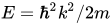

.
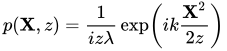
The thickness of each slice over which the iteration is performed is usually small and as a result within a slice the potential field can be approximated to be constant . Subsequently, the modulation function can be represented as:


We can therefore represent the modulation function in the next slice
![{\displaystyle {\begin{aligned}\phi _{n+1}=\phi ({\mathbf {X} },z_{n+1})=[q_{n}\phi _{n}]*p_{n}\end{aligned}}}](https://wikimedia.org/api/rest_v1/media/math/render/svg/4cd834fb9a3642218d1b14d16ef30c8a0f1447af)
where, * represents convolution, and defines the transmission function of the slice.


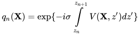
Hence, the iterative application of the aforementioned procedure will provide a full interpretation of the sample in context. Further, it should be reiterated that no assumptions have been made on the periodicity of the sample apart from assuming that the potential is uniform within the slice. As a result, it is evident that this method in principle will work for any system. However, for aperiodic systems in which the potential will vary rapidly along the beam direction, the slice thickness has to be significantly small and hence will result in higher computational expense.

Practical considerations

The basic premise is to calculate diffraction from each layer of atoms using fast Fourier transforms (FFT) and multiplying each by a phase grating term. The wave is then multiplied by a propagator, inverse Fourier transformed, multiplied by a phase grating term yet again, and the process is repeated. The use of FFTs allows a significant computational advantage over the Bloch Wave method in particular, since the FFT algorithm involves pasos comparados con el problema de diagonalización de la solución de onda de Bloch que escala comodóndees el número de átomos en el sistema. (Véase la Tabla 1 para comparar el tiempo de cálculo).


El paso más importante para realizar un cálculo multicapa es configurar la celda unitaria y determinar el grosor adecuado de la capa. En general, la celda unitaria utilizada para simular imágenes será diferente de la que define la estructura cristalina de un material en particular. Esto se debe principalmente a los efectos de aliasing que se producen por errores de envoltura en los cálculos de la transformada rápida de Fourier (FFT). La necesidad de añadir "relleno" adicional a la celda unitaria ha dado lugar a la denominación de "supercelda", y la necesidad de añadir estos píxeles adicionales a la celda unitaria básica conlleva un coste computacional.
Para ilustrar el efecto de elegir un espesor de corte demasiado delgado, consideremos un ejemplo sencillo. El propagador de Fresnel describe la propagación de ondas electrónicas en la dirección z (la dirección del haz incidente) en un sólido:

Dóndees la coordenada de la red recíproca , z es la profundidad en la muestra yes la longitud de onda de la onda electrónica (relacionada con el vector de onda por la relación). En el caso de la aproximación de ángulo pequeño (100 mRad) podemos aproximar el desplazamiento de fase como. Para 100 mRad el errores del orden del 0,5% desdePara ángulos pequeños, esta aproximación se mantiene independientemente de la cantidad de cortes que haya, aunque elegir unUn valor mayor que el parámetro de red (o la mitad del parámetro de red en el caso de las perovskitas ) para una simulación de múltiples capas daría como resultado la ausencia de átomos que deberían estar en el potencial del cristal.



Otras cuestiones prácticas son cómo incluir eficazmente efectos como la dispersión inelástica y difusa, las excitaciones cuantizadas (por ejemplo, plasmones, fonones, excitones), etc. Existía un código que tomaba en consideración estos aspectos mediante un enfoque de función de coherencia [ 12 ] llamado Yet Another Multislice (YAMS), pero dicho código ya no está disponible ni para su descarga ni para su compra.
Software disponible
Existen varios paquetes de software para realizar simulaciones multicorte de imágenes. Entre ellos se encuentran NCEMSS, NUMIS, MacTempas y Kirkland. Existen otros programas, pero lamentablemente muchos no han recibido mantenimiento (por ejemplo, SHRLI81 de Mike O'Keefe del Laboratorio Nacional Lawrence Berkeley y Cerius2 de Accerlys). En la Tabla 2 se presenta una breve cronología de los códigos multicorte, aunque esta lista no es exhaustiva.
ACEM/JCSTEM
This software is developed by Earl Kirkland of Cornell University. This code is freely available as an interactive Java applet and as standalone code written in C/C++. The Java applet is ideal for a quick introduction and simulations under a basic incoherent linear imaging approximation. The ACEM code accompanies an excellent text of the same name by Kirkland which describes the background theory and computational techniques for simulating electron micrographs (including multislice) in detail. The main C/C++ routines use a command line interface (CLI) for automated batching of many simulation. The ACEM package also includes a graphical user interface that is more appropriate for beginners. The atomic scattering factors in ACEM are accurately characterized by a 12-parameter fit of Gaussians and Lorentzians to relativistic Hartree–Fock calculations.
NCEMSS
This package was released from the National Center for High Resolution Electron Microscopy. This program uses a mouse-drive graphical user interface and is written by Roar Kilaas and Mike O’Keefe of Lawrence Berkeley National Laboratory. While the code is no longer developed, the program is available through the Electron Direct Methods (EDM) package written by Laurence D. Marks of Northwestern University. Debye-Waller factors can be included in as a parameter to account for diffuse scattering, although the accuracy is unclear (i.e. a good guess of the Debye-Waller factor is needed).
NUMIS
The Northwestern University Multislice and Imaging System (NUMIS) is a package is written by Laurence Marks of Northwestern University. It uses a command line interface (CLI) and is based on UNIX. A structure file must be provided as input in order to run use this code, which makes it ideal for advanced users. The NUMIS multislice programs use the conventional multislice algorithm by calculating the wavefunction of electrons at the bottom of a crystal and simulating the image taking into account various instrument-specific parameters including and convergence. This program is good to use if one already has structure files for a material that have been used in other calculations (for example, Density Functional Theory). These structure files can be used to general X-Ray structure factors which are then used as input for the PTBV routine in NUMIS. Microscope parameters can be changed through the MICROVB routine.

MacTempas
This software is specifically developed to run in Mac OS X by Roar Kilaas of Lawrence Berkeley National Laboratory. It is designed to have a user-friendly user interface and has been well-maintained relative to many other codes (last update May 2013). It is available (for a fee) from here.
JMULTIS
Este software para simulación multicapa fue escrito en FORTRAN 77 por JM Zuo, durante su etapa como investigador postdoctoral en la Universidad Estatal de Arizona, bajo la dirección de John CH Spence . El código fuente se publicó en el libro Electron Microdiffraction. [ 13 ] En dicho libro también se publicó una comparación entre simulaciones multicapa y de ondas de Bloch para ZnTe. Asimismo, se informó de una comparación independiente entre varios algoritmos multicapa en el año 2000. [ 14 ]
QSTEM
El paquete de software de simulación cuantitativa TEM/STEM (QSTEM) fue desarrollado por Christopher Koch de la Universidad Humboldt de Berlín, Alemania. Permite la simulación de HAADF, ADF, ABF-STEM, así como de TEM convencional y CBED. El ejecutable y el código fuente están disponibles para su descarga gratuita en el sitio web del grupo Koch .
CÉLULAS MADRE
Este código fue escrito por Vincenzo Grillo del Instituto de Nanociencia (CNR) en Italia. Se trata esencialmente de una interfaz gráfica para el código multicapa escrito por Kirkland, con funcionalidades adicionales. Estas incluyen herramientas para generar estructuras cristalinas complejas, simular imágenes HAADF y modelar la sonda STEM, así como modelar la deformación en materiales. También dispone de herramientas para el análisis de imágenes (por ejemplo, GPA) y el filtrado. El código se actualiza con frecuencia con nuevas funcionalidades y se mantiene una lista de correo para usuarios. Está disponible gratuitamente en su sitio web .
SONDA DEL DR.
Simulaciones de imágenes multicorte para microscopía electrónica de transmisión de imágenes coherentes y de escaneo de alta resolución, desarrolladas por Juri Barthel del Centro Ernst Ruska en el Centro de Investigación Jülich . El software incluye una interfaz gráfica de usuario para la visualización directa de los cálculos de imágenes STEM, así como un conjunto de módulos de línea de comandos para tareas de cálculo más complejas. Los programas se han escrito en Visual C++, Fortran 90 y Perl. Los binarios ejecutables para sistemas operativos Microsoft Windows de 32 y 64 bits están disponibles gratuitamente en el sitio web .
clTEM
Software multicorte acelerado por OpenCL, escrito por Adam Dyson y Jonathan Peters de la Universidad de Warwick . clTEM se encuentra en desarrollo desde octubre de 2019.
cudaEM
El código cudaEM es un código compatible con múltiples GPU basado en CUDA para simulaciones multislice, desarrollado por el grupo de Stephen Pennycook.
Extensiones
Multicapa magnética
An extension of the multislice algorithm is the magnetic multislice method, also referred to as the Pauli multislice method, which enables the simulation of electron microscopy of magnetic materials.[15][16] This method is based on the Pauli equation, incorporating the effects of spin and orbital angular momentum of electrons in elastic scattering. Unlike the conventional Schrödinger equation-based multislice approach, the magnetic multislice method explicitly accounts for the interaction of electron beams with the magnetic fields in a solid.
Inelastic scattering: phonons and magnons
The multislice method has been extended to model inelastic scattering mechanisms involving phonons[17] and magnons.[18]
Frozen phonon multislice method
The frozen phonon multislice method (FPMS) was developed to simulate the impact of thermal vibrations on electron diffraction.[17] First introduced in the early 1990s, FPMS approximates phonon-induced distortions by averaging over static snapshots of atomic displacements sampled from thermal distributions.[17][19]
Frozen magnon multislice method
Inspired by FPMS, the frozen magnon multislice method (FMMS) was introduced to model the diffuse scattering of electrons due to spin-wave excitations (magnons).[18] FMMS follows an analogous approach to FPMS but is implemented within the Pauli multislice framework, allowing for the simulation of inelastic magnetic scattering processes.
Electron energy loss and gain spectroscopies: phonons and magnons
Building on FPMS and FMMS, additional theoretical methods have been developed to compute electron energy loss spectroscopy (EELS) and electron energy gain spectroscopy (EEGS) in TEM/STEM:
- Frequency-resolved frozen phonon multislice (FRFPMS): An extension of FPMS, the FRFPMS method incorporates frequency-dependent atomic vibrations to model momentum-resolved phonon EELS signals in TEM/STEM.[20]
- Time autocorrelation of auxiliary wavefunctions (TACAW) method: The TACAW method incorporates a fully dynamical treatment of multiple scattering effects in electron-phonon and electron-magnon interactions. By utilizing the time autocorrelation of auxiliary wavefunctions, this method extends FPMS and FMMS to simulate momentum-resolved EELS and EEGS in TEM/STEM for both phonons and magnons.[21]
References
- 123J. M. Cowley and A. F. Moodie (1957). "The Scattering of Electrons by Atoms and Crystals. I. A New Theoretical Approach". Acta Crystallographica. Vol. 10.
- ↑John M. Cowley (1995). Diffraction Physics, 3rd Ed. North Holland Publishing Company.
- ↑Ishizuka, Kazuo (2004). "FFT Multislice Method—The Silver Anniversary". Microscopy and Microanalysis. 10 (1): 34–40. doi:10.1017/S1431927604040292. ISSN 1431-9276.
- ↑Dr. Earl J. Kirkland. Advanced Computing in Electron Microscopy.
- ↑Metherell, A. J. (1975). Electron Microscopy in Materials Science: Part II. Commission of the European Communities. pp. 397–552.
- ↑Bethe, H. (1928). "Theorie der Beugung von Elektronen an Kristallen". Annalen der Physik (in German). 392 (17): 55–129. doi:10.1002/andp.19283921704.
- 12Peng, L.-M.; Dudarev, S. L.; Whelan, M. J. (2011). High energy electron diffraction and microscopy. Monographs on the physics and chemistry of materials (1. publ. in paperback ed.). Oxford: Oxford Univ. Press. ISBN 978-0-19-960224-7.
- ↑P. Goodman and A. F. Moodie, Acta Crystallogr. 1974, A30, 280
- ↑Hirsch, P. B., ed. (1971). Electron microscopy of thin crystals (4. impression ed.). London: Butterworth. ISBN 978-0-408-18550-9.
- ↑Sturkey, Lorenzo (1962). "The Calculation of Electron Diffraction Intensities". Proceedings of the Physical Society. 80 (2): 321–354. doi:10.1088/0370-1328/80/2/301. ISSN 0370-1328.
- ↑John C. H. Spence (2013). High-Resolution Electron Microscopy, 4th Ed. Oxford University Press.
- ↑Heiko Muller (2000). A Coherence Function Approach to Image Simulation (Ph.D.). Vom Fachbereich Physik Technischen Universitat Darmstadt.
- ↑Electron Microdiffraction, J.C. H. Spence and J. M. Zuo, Plenum, New York, 1992
- ↑Koch, C. and J.M. Zuo, “Comparison of multislicecomputer programs for electron scattering simulations and the Bloch wavemethod”, Microscopy and Microanalysis, Vol. 6 Suppl. 2, 126-127, (2000).
- ↑Edström, Alexander; Lubk, Axel; Rusz, Ján (2016-11-07). "Magnetic effects in the paraxial regime of elastic electron scattering". Physical Review B. 94 (17). arXiv:1607.01230. doi:10.1103/PhysRevB.94.174414. ISSN 2469-9950.
- ↑Edström, Alexander; Lubk, Axel; Rusz, Ján (2019-05-28). "Quantum mechanical treatment of atomic-resolution differential phase contrast imaging of magnetic materials". Physical Review B. 99 (17). arXiv:1903.03083. doi:10.1103/PhysRevB.99.174428. ISSN 2469-9950.
- 123Loane, R. F.; Xu, P.; Silcox, J. (1991-05-01). "Thermal vibrations in convergent-beam electron diffraction". Acta Crystallographica Section A: Foundations of Crystallography. 47 (3): 267–278. doi:10.1107/S0108767391000375. ISSN 0108-7673.
- 12Lyon, Keenan; Bergman, Anders; Zeiger, Paul; Kepaptsoglou, Demie; Ramasse, Quentin M.; Idrobo, Juan Carlos; Rusz, Ján (2021-12-13). "Theory of magnon diffuse scattering in scanning transmission electron microscopy". Physical Review B. 104 (21). arXiv:2105.04467. doi:10.1103/PhysRevB.104.214418. ISSN 2469-9950.
- ↑Van Dyck, D. (May 2009). "Is the frozen phonon model adequate to describe inelastic phonon scattering?". Ultramicroscopy. 109 (6): 677–682. doi:10.1016/j.ultramic.2009.01.001.
- ↑Zeiger, Paul M.; Rusz, Ján (2020-01-13). "Efficient and Versatile Model for Vibrational STEM-EELS". Physical Review Letters. 124 (2). arXiv:1909.03982. doi:10.1103/PhysRevLett.124.025501. ISSN 0031-9007.
- ↑Castellanos-Reyes, José Ángel; Zeiger, Paul M.; Rusz, Ján (2025-01-22). "Dynamical Theory of Angle-Resolved Electron Energy Loss and Gain Spectroscopies of Phonons and Magnons in Transmission Electron Microscopy Including Multiple Scattering Effects". Physical Review Letters. 134 (3). arXiv:2401.15599. doi:10.1103/PhysRevLett.134.036402. ISSN 0031-9007.
- Microscopy
- Mathematical modeling


